Blog

RED Brick in EMC laboratory

Yesterday we were in an EMC (electromagnetic compatibility measures) laboratory.

https://www.tinkerforge.com/static/img/_stuff/brick_red_emi3_786.jpg

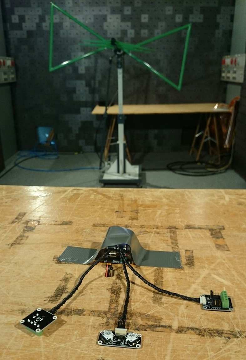
We did an preliminary EMI (electromagnetic interference) test of the RED Brick prototype. As a first test we put the RED Brick alone without any other components in the chamber. The RED Brick was running and just doing CPU cycles on its own.

https://www.tinkerforge.com/static/img/_stuff/brick_red_emi1_786.png

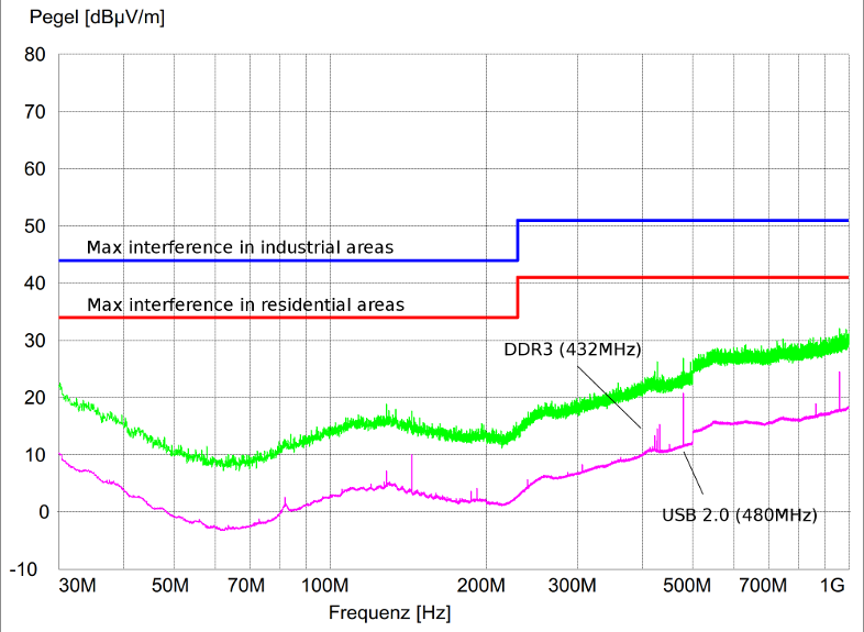
The result was phenomenal! It was beyond our expectation, during the run we temporary thought that something with the test chamber was not in order. But it turns out that everything worked and the RAM, oscillator and similar are routed very well. They nearly don’t show up at all!

As a next test we tested a stack comprised of Step-Down Power Supply, RED Brick and Master Brick.

https://www.tinkerforge.com/static/img/_stuff/brick_red_emi2_786.png

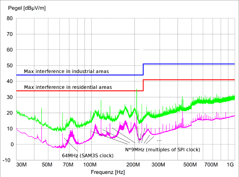
Here you can clearly see the SPI stack communication, since all of the peaks are a multiple of 9MHz (the frequency that we use for SPI). However, the result is still very good.

The green line is the absolut maximum measurement, while the magenta line is an average. For the real measurements that we will do with the final version of the RED Brick the quasi-peak will be measured. This will lie somewhere in the middle of both lines.

Unfortunately we were not expecting the phenomenal result of the RED Brick alone, so we weren’t well prepared for the stack tests. The RED Brick has resistors in the SPI traces that can affect the edge steepness. The RED Brick that we used for testing had 0 ohm resistor soldered in place. The next time we are in the EMC laboratory we will try out different resistor values to further decrease the interference that comes from the SPI communication.

However, all in all we can now already be completely sure that we will be able to issue a CE certificate for the final version of the RED Brick. This is very good news, we weren’t even expecting results this good!

We will now be able to order circuit boards for the next prototype. We hope that this prototype will already be the final version of the RED Brick. In the new prototype we incorporate the following changes:

  • Reset button is now connected to GPIO and will halt the Linux properly.

  • We can now reset the stack that is on top of the RED Brick via software, this makes it possible for brickd to restart the stack when it is started the first time to get the Bricks in a known state.

  • JTAG hardware is now configured correctly.

  • We use an inverter on the serial RTS line and fix CTS to ground to be able to control the RS485 Extension more easily.

  • Fix wrong wiring in power supply.

  • Pick-and-place-ability improved.

  • USB ESD protection circuit error fixed.

After these test results we are confident that we will have the RED Brick in our shop this year. So stay tuned!

MakerBeam at Tinkerforge

As of now you can by MakerBeams in our shop! It is the perfect mounting solution for Bricks, Bricklets & Co.

http://download.tinkerforge.com/makerbeam/images/maker_beam_stepper_600.jpg

MakerBeam is a versatile and lightweight structural system with a cross section of 10x10mm. It has endless building possibilities in desktop size and uses Mini-T, which is a smaller version of the T-Slot standard that is widely used in industrial automation. Each beam has a 8mm deep 2.5mm diameter threaded hole on both ends, sized for normal M3 screws. The profile system is very light, each millimeter of beam has a weight of only 0.136g. You can use MakerBeam to build the mechanical structure for robots, CNC projects, camera sliders and other cool projects! The official MakerBeam website has a big list of example projects.

http://download.tinkerforge.com/makerbeam/images/maker_beam_servo_600.jpg

With MakerBeams we are extending our range of accessories. As a next step we want to add motors (stepper, servo, dc). We are currently testing different motors from different manufacturers, stay tuned!

As soon as we received the first beams and brackets we of course had to start tinkering with them immediately ;-). We were able to mount different Bricks and Bricklets into a frame in no time:

http://download.tinkerforge.com/makerbeam/images/maker_beam_cube1_600.jpg

This thing would be doing well as a satellite, don’t you think?

http://download.tinkerforge.com/makerbeam/images/maker_beam_satellite2.jpg

New Bricklets: Color, NFC/RFID and Solid State Relay

We used your feedback to design three new Bricklets. All three of them have been released today including lots of accessories:

1) Color Bricklet

https://www.tinkerforge.com/en/doc/_images/Bricklets/bricklet_color_in_action_600.jpg

The Color Bricklet uses a precision color sensor. The sensor can measure RGB color, color temperature and Illuminance with a resolution of 16 bit each! It is possible to enable a defined lightning (by an LED) via software. Using the LED makes it possible to measure the light reflection of an object with high precision and repeatability. A usage for the Bricklet is for example the sorting of objects. While the Ambient Light Bricklet can measure up to ~1000 Lux, the new Color Bricklet can measure values of several 10000 Lux without any problems.

2) NFC/RFID Bricklet

https://www.tinkerforge.com/en/doc/_images/Bricklets/bricklet_nfc_rfid_tilted_600.jpg

With the NFC/RFID Bricklet you can read and write different 13.56MHz NFC or RFID tags. The Bricklet supports Mifare Classic, NFC Forum Type 1 and 2 RFID/NFC tags with an arbitrary amount of memory. Suitable tags in the form of cards, keyfobs and stickers can be found in our shop. As an example you could build an intelligent cat door with this Bricklet. It could log the enter/leave times, twitter it and similar :-). We have lots of ideas for interesting projects for this product! This example is also good to explain an important feature of NFC: The range is limited to 10cm. The cat door should of course not open itself if the cat is only roughly in the vicinity.

3) Solid State Relay Bricklet

https://www.tinkerforge.com/en/doc/_images/Bricklets/bricklet_ssr_w_heatsink_tilted_600.jpg

Switching big loads, such as motors, can be problematic. Currently it is possible to use the Dual Relay Bricklet to switch voltages. But especially big 230V loads can be problematic if switched with a mechanical relay. Switching sparks can easily lead to unstable systems. In this case it is possible to use a Snubber (see Dual Relay Bricklet documentation). It is however easier to use a solid state relay. A solid state relay does not switch mechanically, it is a completely electronic switch. Thus there are no switching sparks present whatsoever. A solid state relay also has more switching cycles (it is wear-free) because no mechanical parts are used. It also has a galvanic isolation between the controlling (input) and the load (output).

It is very easy to switch these relays with the Solid State Relay Bricklet. We are offering two different types of relays. One can switch alternating current of up to 25A at 380V and the other can switch direct current of up to 50V at 80A. Additionally we have a cover that can protect you against touching the contacts as well as a heatsink that is necessary if you want to switch big loads.

We tested different types and manufacturers of solid state relays. Please note that the relays in our shop are of high quality compared to some of the super cheap relays that can be bought in china. Although the Bricklet might be compatible to these super cheap relays (at least if you solder a wire to it), we would highly recommend to not use a 2$ relay. We learned our lesson while testing a cheap solid state relay with our electronic load.

Fully automatic photography turntable

By this time we have lots of experience in making photos for the documentation and the shop. Our equipment got steadily better over time. What we were still missing was a turntable that would allow us to make 360° pictures. A professional photography turntable is super expensive, so we made our own!

In front we will show you the resulting 360° photo of the finished turntable and a small video that shows it in action (the video is of low quality, we took it with a smart phone, the camera was used otherwise for obvious reasons ;-) ).

360° Photography of a Bricklet.

From the system of Tinkerforge building blocks we used a Industrial Quad Relay Bricklet and a Stepper Brick. The source code that controls the Stepper Brick and the Quad Relay Bricklet can be found on github.

There are only a few ingredients needed to build a turntable:

https://www.tinkerforge.com/static/img/_stuff/photography_turn_table_1.jpg

We used a stepper motor (14€) and a hub (6€) from Pololu as well as two cutting boards (1€, 3€) as table and foot. In addition we bought a rotary ball bearing from ebay (10€) and we use a few wood offcuts as spacer and brackets/screws from our scrap box.

In sum: Not too expensive!

After we screwed the ball bearing to the top board, the stepper brick to the hub, the spacers to the bottom board, as well as the brackets between the spacers, the whole assembly looks as follows:

https://www.tinkerforge.com/static/img/_stuff/photography_turn_table_2.jpghttps://www.tinkerforge.com/static/img/_stuff/photography_turn_table_3.jpg

You probably noticed that the screws that connect the rotary ball bearing to the top board are not completely screwed in. This was unfortunately necessary because of the high quality of the ball bearing. The ball bearing, which we bought used from ebay is super smooth-running, it can carry 250kg and it has no clearance whatsoever. The latter turned out to be a problem.

Since the hub is directly connected to the stepper motor which in turn has its place because of the position of the ball bearing, the hub has to be perfectly in the middle of the ball bearing. If it is off by only 0.5mm the ball bearing will not turn. Oooops! Despite many tries to screw the hub exactly to the middle, we couldn’t do it as precise as needed. To fix the issue we gave the ball bearings a bit of clearance by not screwing it completely firm to the top board.

Now we have a turntable that we can control to drive to an arbitrary position. For a full automation we also need a possibility to automatically take a photograph. The trigger of our Canon 500D can be driven by a small 2.5mm audio jack. This jack has two strands and shielding. To focus we can connect the shield to the red strand and to trigger a photograph we can connect it to the white strand.

https://www.tinkerforge.com/static/img/_stuff/photography_turn_table_4.jpghttps://www.tinkerforge.com/static/img/_stuff/photography_turn_table_5.jpghttps://www.tinkerforge.com/static/img/_stuff/photography_turn_table_6.jpg

We opened up an audio jack cable and gave the strands and the shielding some wire end sleeves. The resulting four wires can be connected to the Industrial Quad Relay Bricklet. Now we can trigger a photograph by switching relay 1 and we can focus be switching relay 2. That was easy!

The end result with a white photo pad on top of the board looks as follows:

https://www.tinkerforge.com/static/img/_stuff/photography_turn_table_7.jpg

It fits like a charm in our (of course also self-made) photo booth!

https://www.tinkerforge.com/static/img/_stuff/photography_turn_table_8.jpg