- Getting Started
- Hardware
- Bricks
- Bricklets
- Master Extensions
- Power Supplies
- Discontinued Products
- Bricks
- Bricklets
- Accelerometer Bricklet
- Ambient Light Bricklet
- Ambient Light Bricklet 2.0
- Analog In Bricklet
- Analog In Bricklet 2.0
- Analog Out Bricklet
- CO2 Bricklet
- Current12 Bricklet
- Current25 Bricklet
- Distance US Bricklet
- Dual Button Bricklet
- Dual Relay Bricklet
- GPS Bricklet
- Humidity Bricklet
- Industrial Analog Out Bricklet
- Industrial Digital In 4 Bricklet
- Industrial Dual Analog In Bricklet
- Industrial Quad Relay Bricklet
- IO-4 Bricklet
- Laser Range Finder Bricklet
- LCD 16x2 Bricklet
- LED Strip Bricklet
- Load Cell Bricklet
- Moisture Bricklet
- Motion Detector Bricklet
- NFC/RFID Bricklet
- OLED 128x64 Bricklet
- Piezo Buzzer Bricklet
- PTC Bricklet
- PTC Bricklet 2.0
- Remote Switch Bricklet
- RGB LED Bricklet
- RGB LED Matrix Bricklet
- Rotary Encoder Bricklet
- Solid State Relay Bricklet
- Temperature IR Bricklet
- Thermocouple Bricklet
- UV Light Bricklet
- Voltage Bricklet
- Voltage/Current Bricklet
- Master Extensions
- Timeline
- Software
- Kits
- Embedded Boards
- Specifications
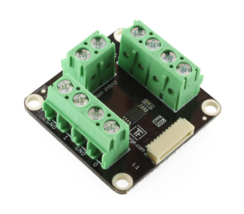
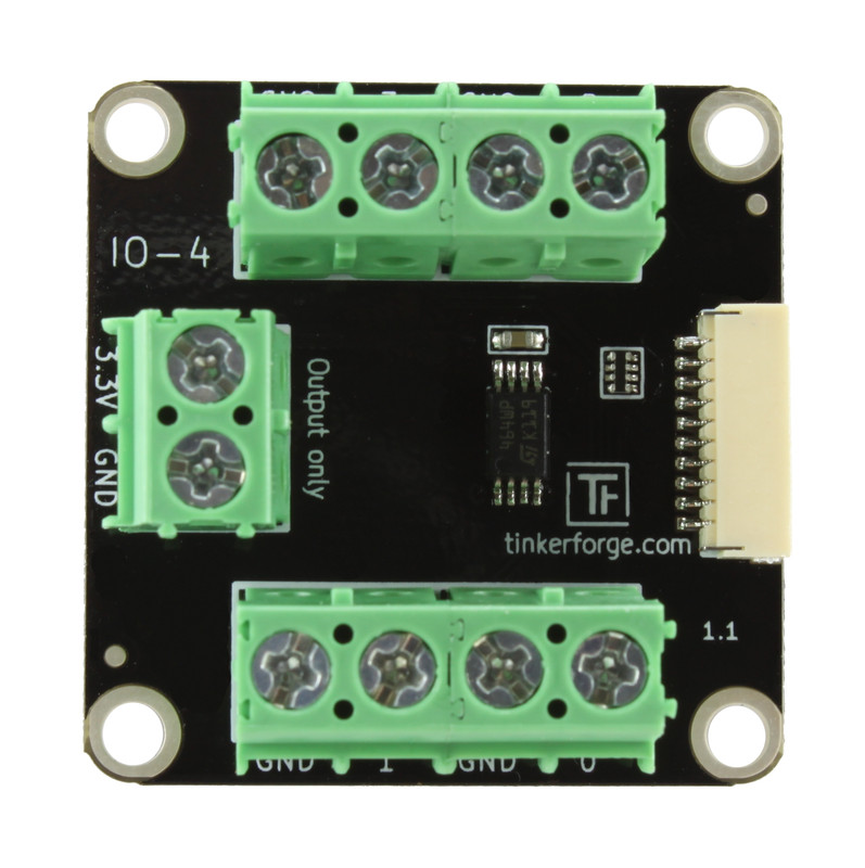
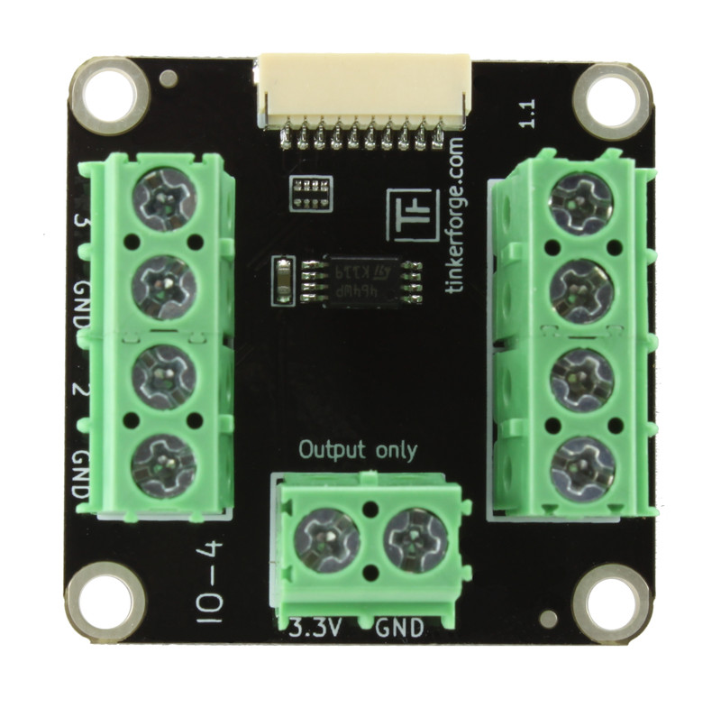
IO-4 Bricklet
Note
The IO-4 Bricklet is discontinued and is no longer sold. The IO-4 Bricklet 2.0 is the recommended replacement.
Features
- 4-channel digital input/output
- Fixed 3.3V logic voltage
- Configurable pull-ups and interrupts
Description
The IO-4 Bricklet can be used to extend the features of Bricks by external digital inputs and outputs.
The Bricklet features 4 I/O pins that can be independently configured as digital inputs or outputs. Each input pin can additionally be configured with a pull-up or as interrupt source. Via terminal blocks all signals can be accessed. Two additional terminal blocks deliver 3.3V and GND.
Human interfaces, such as switches, push-buttons and LEDs are typical applications of this Bricklet.
Hardware version 1.1 adds GND pins nearby the 4 I/O pins to allow easier access between I/O pins and GND.
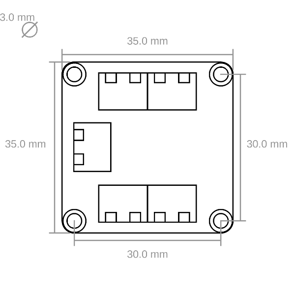
Technical Specifications
| Property | Value |
|---|---|
| I/O Pins | 4 |
| Current Consumption | 1mA |
| I/O Voltages | Fixed 3.3V |
| Maximum Output Current | 6mA (per output pin), 100mA (3.3V fixed output pin) |
| Maximum API Calls* | set-value (1kHz), get-value (0.5kHz), callbacks (1kHz) |
| Dimensions (W x D x H) | 35 x 35 x 14mm (1.38 x 1.38 x 0.55") |
| Weight | 14g |
* depends on your system (OS, CPU etc.)
Resources
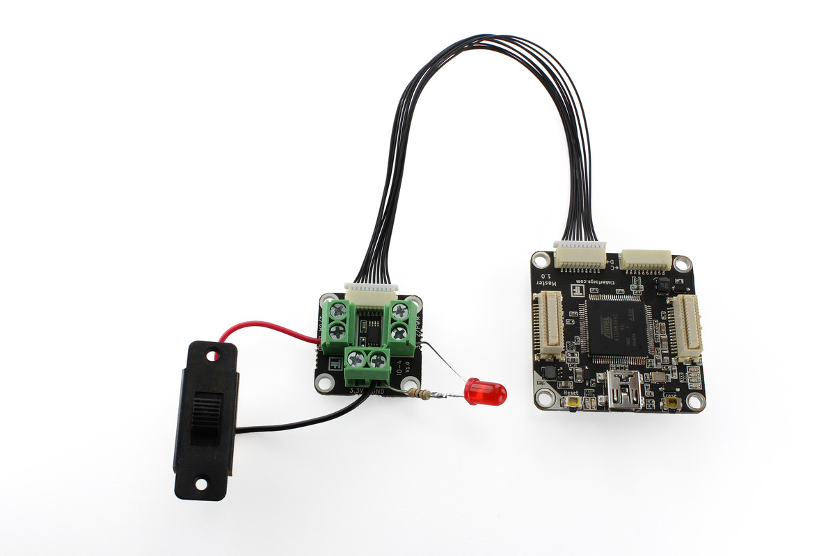
Test your IO-4 Bricklet
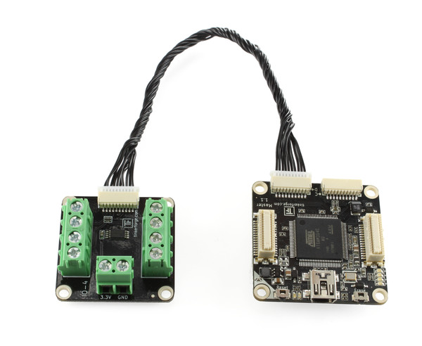
To test a IO-4 Bricklet you need to have Brick Daemon and Brick Viewer installed. Brick Daemon acts as a proxy between the USB interface of the Bricks and the API bindings. Brick Viewer connects to Brick Daemon. It helps to figure out basic information about the connected Bricks and Bricklets and allows to test them.
Connect the IO-4 Bricklet to a Brick with a Bricklet Cable. In our test we connected an LED with series resistor to the board by attaching the anode to pin 3 and the cathode to a GND pin. Additionally we connected a slide switch that can short pin 0 to GND (see picture below).
Starting from hardware version 1.1 you can also use the GND pins directly beside the I/O pins.
If you connect the Brick to the PC over USB, you should see a new tab named "IO-4 Bricklet" in the Brick Viewer after a moment. Select this tab.
If everything went as expected the Brick Viewer should look as depicted below.
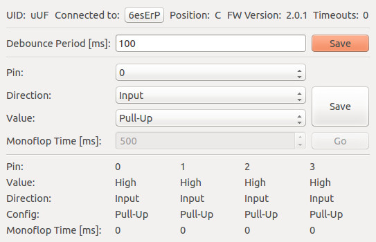
In this tab you can change the "Debounce Period", it is the debounce time for interrupt callbacks. For example: If you set this value to 100, you will get interrupts maximal every 100ms. This is necessary if something that bounces is connected to the IO-4 Bricklet, such as a button. You can test the optimal value in the Brick Viewer and use it later in your own program.
Below the debounce period configuration you can configure the pins. Each pin can be configured as input/output and in case of an input pin as pull-up. The current state is depicted in the table below.
To test the LED we configure pin 3 as output and change the value. When the pin is high the LED should light up. To test the button configure pin 0 as input pull-up. We need the pull-up to define a stable state when the slide switch does not short pin 0 to GND. Now look in the table, you should see that you can change the value of the pin by toggling the slide switch.
If you don't have a button or a LED you can try to measure voltages with a voltage meter or connect an input pin with GND or VCC to see changes in the Brick Viewer.
After this test you can go on with writing your own application. See the Programming Interface section for the API of the IO-4 Bricklet and examples in different programming languages.
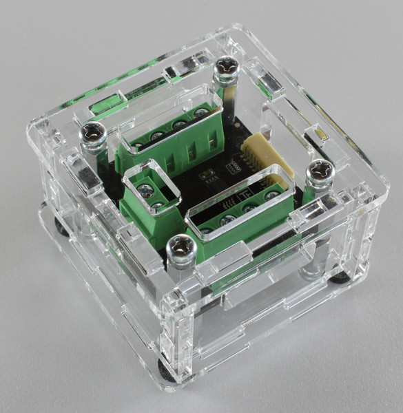
Case
A laser-cut case for the IO-4 Bricklet is available.

The assembly is easiest if you follow the following steps:
- Screw spacers to the Bricklet,
- screw bottom plate to bottom spacers,
- build up side plates,
- plug side plates into bottom plate and
- screw top plate to top spacers.
Below you can see an exploded assembly drawing of the IO-4 Bricklet case:
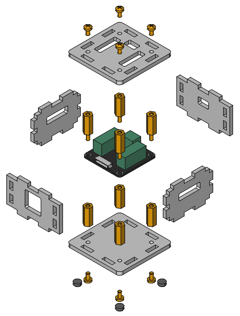
Hint: There is a protective film on both sides of the plates, you have to remove it before assembly.
Programming Interface
See Programming Interface for a detailed description.
| Language | API | Examples | Installation |
|---|---|---|---|
| C/C++ | API | Examples | Installation |
| C# | API | Examples | Installation |
| Delphi/Lazarus | API | Examples | Installation |
| Go | API | Examples | Installation |
| Java | API | Examples | Installation |
| JavaScript | API | Examples | Installation |
| LabVIEW | API | Examples | Installation |
| Mathematica | API | Examples | Installation |
| MATLAB/Octave | API | Examples | Installation |
| MQTT | API | Examples | Installation |
| openHAB | API | Examples | Installation |
| Perl | API | Examples | Installation |
| PHP | API | Examples | Installation |
| Python | API | Examples | Installation |
| Ruby | API | Examples | Installation |
| Rust | API | Examples | Installation |
| Shell | API | Examples | Installation |
| Visual Basic .NET | API | Examples | Installation |
| TCP/IP | API | ||
| Modbus | API |