- Getting Started
- Hardware
- Bricks
- Bricklets
- Accelerometer Bricklet 2.0
- Air Quality Bricklet
- Ambient Light Bricklet 3.0
- Analog In Bricklet 3.0
- Analog Out Bricklet 3.0
- Barometer Bricklet
- Barometer Bricklet 2.0
- Breakout Bricklet
- CAN Bricklet
- CAN Bricklet 2.0
- CO2 Bricklet 2.0
- Color Bricklet
- Color Bricklet 2.0
- Compass Bricklet
- DC Bricklet 2.0
- Distance IR Bricklet
- Distance IR Bricklet 2.0
- Distance US Bricklet 2.0
- DMX Bricklet
- Dual Button Bricklet 2.0
- Dust Detector Bricklet
- E-Paper 296x128 Bricklet
- Energy Monitor Bricklet
- GPS Bricklet 2.0
- GPS Bricklet 3.0
- Hall Effect Bricklet
- Hall Effect Bricklet 2.0
- Humidity Bricklet 2.0
- IMU Bricklet 3.0
- Industrial Analog Out Bricklet 2.0
- Industrial Counter Bricklet
- Industrial Digital In 4 Bricklet 2.0
- Industrial Digital Out 4 Bricklet
- Industrial Digital Out 4 Bricklet 2.0
- Industrial Dual 0-20mA Bricklet
- Industrial Dual 0-20mA Bricklet 2.0
- Industrial Dual AC In Bricklet
- Industrial Dual AC Relay Bricklet
- Industrial Dual Analog In Bricklet 2.0
- Industrial Dual Relay Bricklet
- Industrial PTC Bricklet
- Industrial Quad Relay Bricklet 2.0
- IO-16 Bricklet
- IO-16 Bricklet 2.0
- IO-4 Bricklet 2.0
- Isolator Bricklet
- Joystick Bricklet
- Joystick Bricklet 2.0
- Laser Range Finder Bricklet 2.0
- LCD 128x64 Bricklet
- LCD 20x4 Bricklet
- LED Strip Bricklet 2.0
- Line Bricklet
- Linear Poti Bricklet
- Linear Poti Bricklet 2.0
- Load Cell Bricklet 2.0
- Motion Detector Bricklet 2.0
- Motorized Linear Poti Bricklet
- Multi Touch Bricklet
- Multi Touch Bricklet 2.0
- NFC Bricklet
- OLED 128x64 Bricklet 2.0
- OLED 64x48 Bricklet
- One Wire Bricklet
- Outdoor Weather Bricklet
- Particulate Matter Bricklet
- Performance DC Bricklet
- Piezo Speaker Bricklet
- Piezo Speaker Bricklet 2.0
- Real-Time Clock Bricklet
- Real-Time Clock Bricklet 2.0
- Remote Switch Bricklet 2.0
- RGB LED Bricklet 2.0
- RGB LED Button Bricklet
- Rotary Encoder Bricklet 2.0
- Rotary Poti Bricklet
- Rotary Poti Bricklet 2.0
- RS232 Bricklet
- RS232 Bricklet 2.0
- RS485 Bricklet
- Segment Display 4x7 Bricklet
- Segment Display 4x7 Bricklet 2.0
- Servo Bricklet 2.0
- Silent Stepper Bricklet 2.0
- Solid State Relay Bricklet 2.0
- Sound Intensity Bricklet
- Sound Pressure Level Bricklet
- Temperature Bricklet
- Temperature Bricklet 2.0
- Temperature IR Bricklet 2.0
- Thermal Imaging Bricklet
- Thermocouple Bricklet 2.0
- Tilt Bricklet
- UV Light Bricklet 2.0
- Voltage/Current Bricklet 2.0
- XMC1400 Breakout Bricklet
- Master Extensions
- Power Supplies
- Discontinued Products
- Timeline
- Software
- Kits
- Embedded Boards
- Specifications
IO-4 Bricklet 2.0
Features
- 4-channel digital input/output
- Fixed 3.3V logic voltage
- Configurable pull-ups and interrupts
- PWM output with frequency up to 32MHz
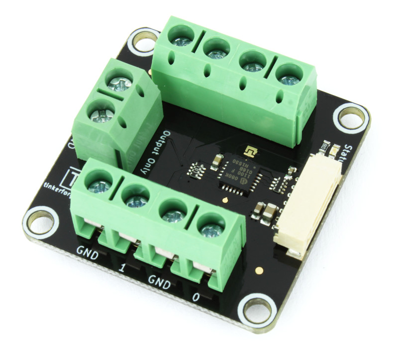
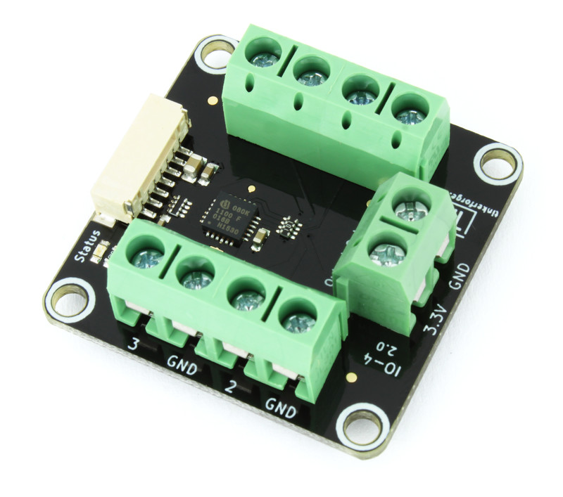
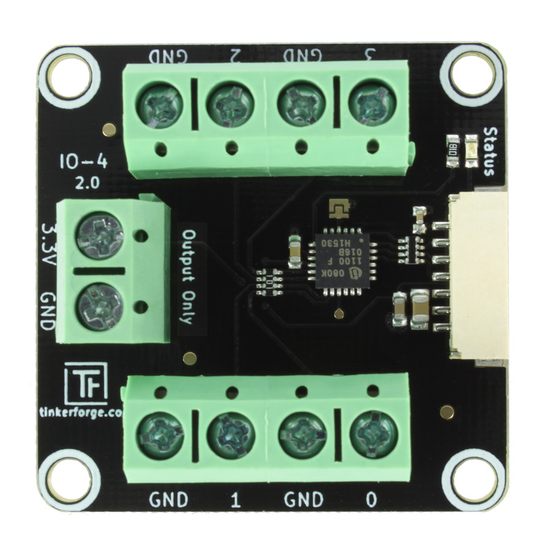
Description
The IO-4 Bricklet 2.0 can be used to extend the features of Bricks by external digital inputs and outputs.
The Bricklet features 4 I/O pins that can be independently configured as digital inputs or outputs. Each input pin can additionally be configured with a pull-up or as interrupt source. Via terminal blocks all signals can be accessed. Two additional terminal blocks deliver 3.3V and GND.
Human interfaces, such as switches, push-buttons and LEDs are typical applications of this Bricklet.
This Bricklet ist not galvanically isolated to the Tinkerforge system. This means that there is a direct electrical connection between the terminals of the Bricklet and the rest of the system. Dependent of the application this can lead to undesired connections, ground loops or short circuits. These problems can be prevented by using the Bricklet together with a Isolator Bricklet.
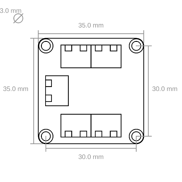
Technical Specifications
| Property | Value |
|---|---|
| I/O Pins | 4 |
| Current Consumption | 30mW (6mA at 5V) |
| I/O Voltages | Fixed 3.3V |
| Port Protection | 82 Ohm series resistor |
| Maximum API Calls* | set-value (1kHz), get-value (0.5kHz), callbacks (1kHz) |
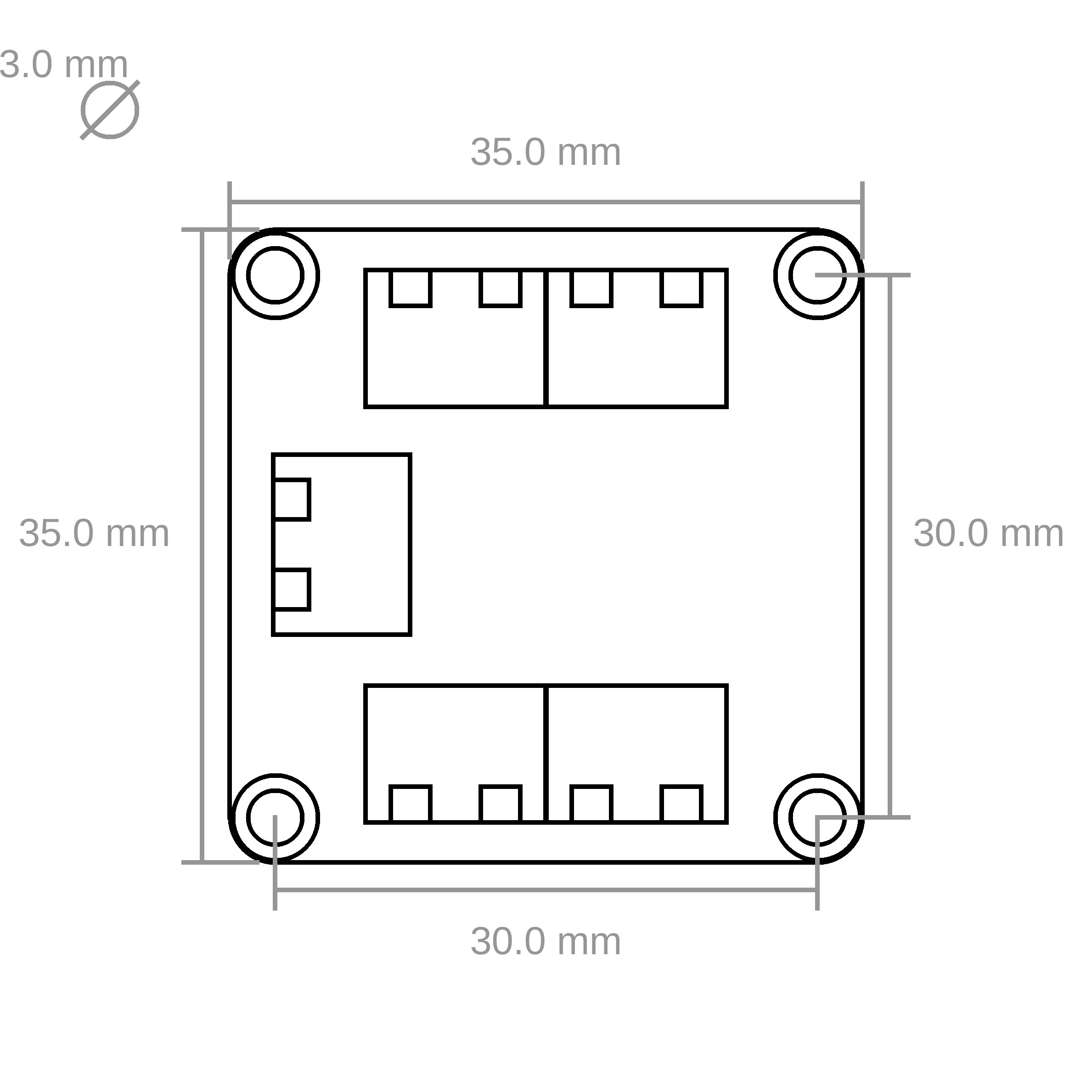
| Dimensions (W x D x H) | 35 x 35 x 14mm (1.38 x 1.38 x 0.55") |
| Weight | 15g |
* depends on your system (OS, CPU etc.)
Resources
Test your IO-4 Bricklet 2.0
To test a IO-4 Bricklet 2.0 you need to have Brick Daemon and Brick Viewer installed. Brick Daemon acts as a proxy between the USB interface of the Bricks and the API bindings. Brick Viewer connects to Brick Daemon. It helps to figure out basic information about the connected Bricks and Bricklets and allows to test them.
Connect the IO-4 Bricklet 2.0 to a Brick with a Bricklet Cable.
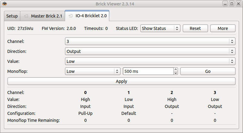
If you connect the Brick to the PC over USB, you should see a new tab named "IO-4 Bricklet 2.0" in the Brick Viewer after a moment. Select this tab. If everything went as expected the Brick Viewer should look as depicted below.
After this test you can go on with writing your own application. See the Programming Interface section for the API of the IO-4 Bricklet 2.0 and examples in different programming languages.
Each channel can be configured as input/output and in case of an input pin as pull-up. The current state is depicted in a table.
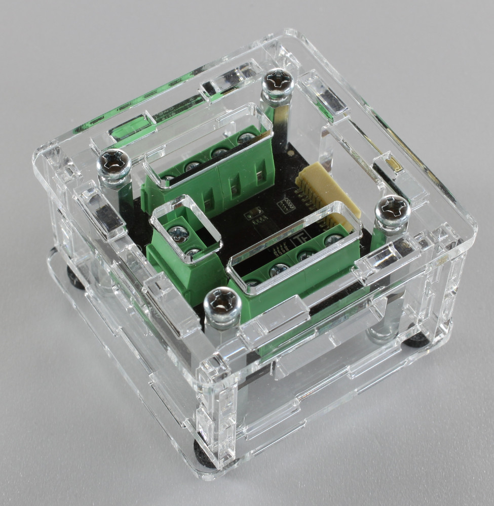
Case
A laser-cut case for the IO-4 Bricklet 2.0 is available.
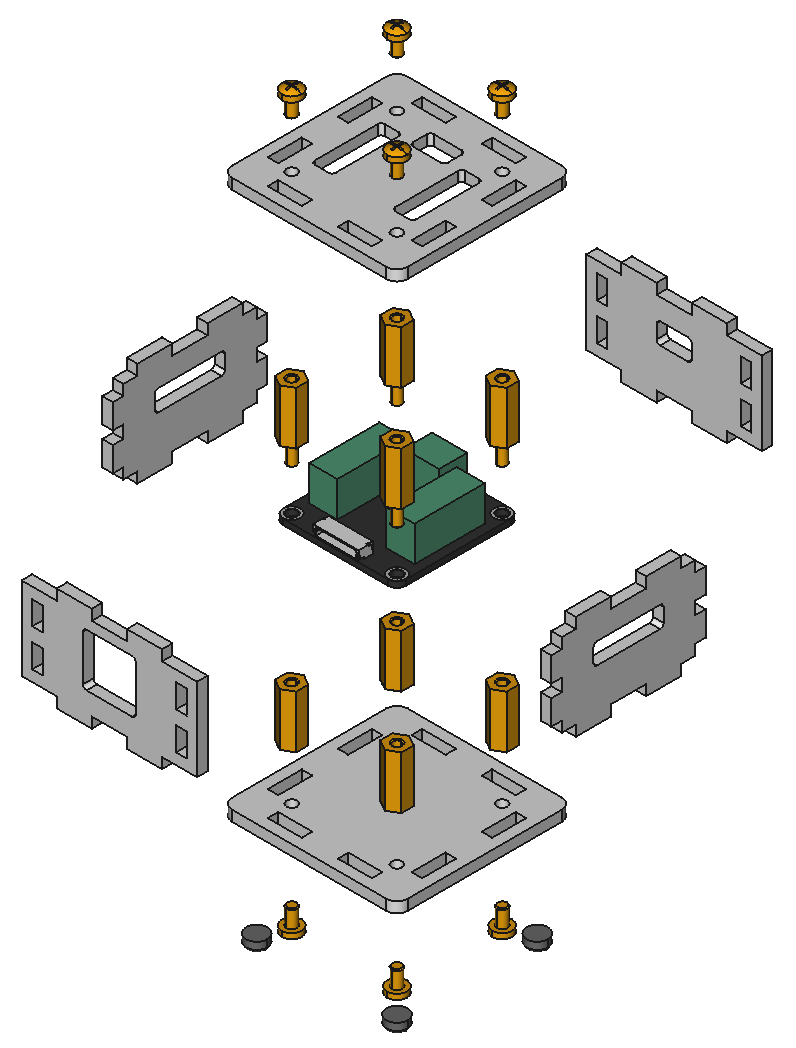
The assembly is easiest if you follow the following steps:
- Screw spacers to the Bricklet,
- screw bottom plate to bottom spacers,
- build up side plates,
- plug side plates into bottom plate and
- screw top plate to top spacers.
Below you can see an exploded assembly drawing of the IO-4 Bricklet 2.0 case:
Hint: There is a protective film on both sides of the plates, you have to remove it before assembly.
Programming Interface
See Programming Interface for a detailed description.
| Language | API | Examples | Installation |
|---|---|---|---|
| C/C++ | API | Examples | Installation |
| C/C++ for Microcontrollers | API | Examples | Installation |
| C# | API | Examples | Installation |
| Delphi/Lazarus | API | Examples | Installation |
| Go | API | Examples | Installation |
| Java | API | Examples | Installation |
| JavaScript | API | Examples | Installation |
| LabVIEW | API | Examples | Installation |
| Mathematica | API | Examples | Installation |
| MATLAB/Octave | API | Examples | Installation |
| MQTT | API | Examples | Installation |
| openHAB | API | Examples | Installation |
| Perl | API | Examples | Installation |
| PHP | API | Examples | Installation |
| Python | API | Examples | Installation |
| Ruby | API | Examples | Installation |
| Rust | API | Examples | Installation |
| Shell | API | Examples | Installation |
| Visual Basic .NET | API | Examples | Installation |
| TCP/IP | API | ||
| Modbus | API |