- Getting Started
- Hardware
- Software
- Kits
- Starter Kit: Weather Station
- Starter Kit: Hardware Hacking
- Starter Kit: Server Room Monitoring
- Starter Kit: Server Room Monitoring 2.0
- Starter Kit: Blinkenlights
- Starter Kit: Internet of Things
- Starter Kit: Camera Slider
- Tabletop Weather Station
- Embedded Boards
- Specifications
Construction of Starter Kit: Blinkenlights
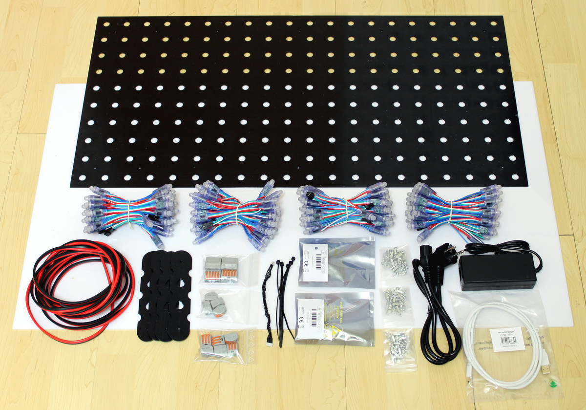
The Starter Kit: Blinkenlights comes with:
- 1x Master Brick,
- 1x LED Strip Bricklet,
- 4x LED Pixels (50 pieces each),
- 1x Perforated Board 80x40cm (black)
- 1x Front Panel 90x50cm (white)
- 4x Wall Mounting Plate (for wall peg)
- 1x 5V/8A Power Supply
- 1x Bricklet Cable 15cm
- 1x 2x2.5mm² wires (5m)
- 2x Dowel and wall peg
- 4x 2-wire clamps
- 6x 3-wire clamps
- 4x 5-wire clamps
and cable straps, screws, spacers and some other parts.
Necessary Tools
You will need a Phillips screwdriver, something to dismantle wires (knife or cable stripper) and a tape measure. Allow some extra time to build the kit.
First Step
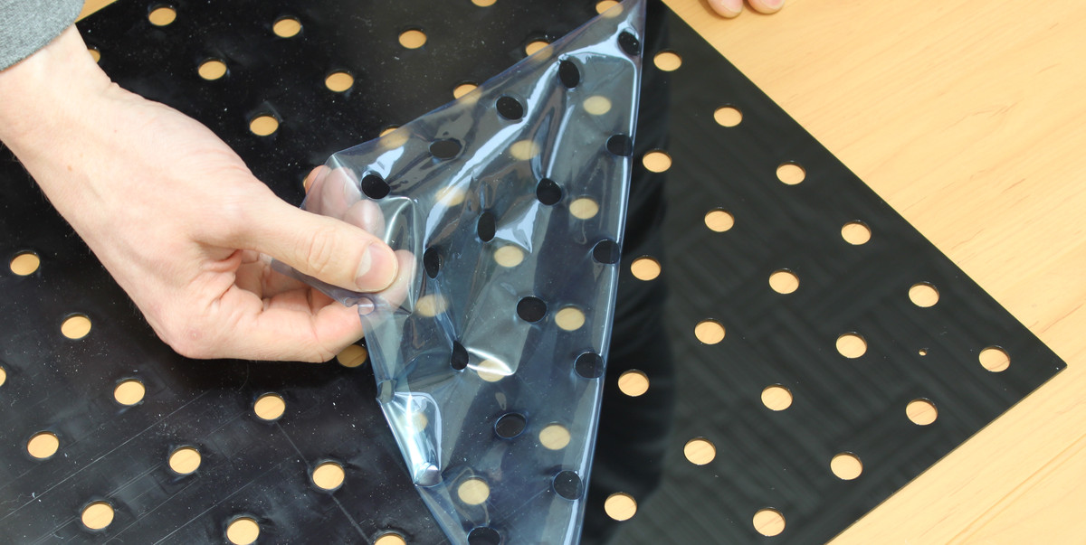
Check if everything was delivered correctly. Remove the protective foil of the front and back of the front panel (white) and the perforated board (black). There is a protective foil on each side of the panel/board.
Attach Pixels to Perforated Board
Next you can stick the pixels into the perforated board. It is important that you start with the correct pixel on the correct position. If you start wrong it is possible that you can't wire the pixels or that the cable wiring will not work as intended.
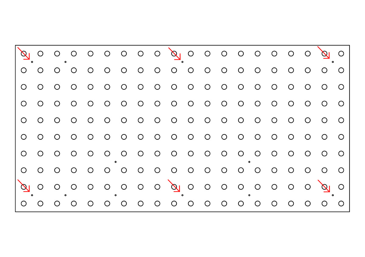
Take the first bunch of pixels and insert the pixel with the plug (the end that will be connected to the LED Strip Bricklet).
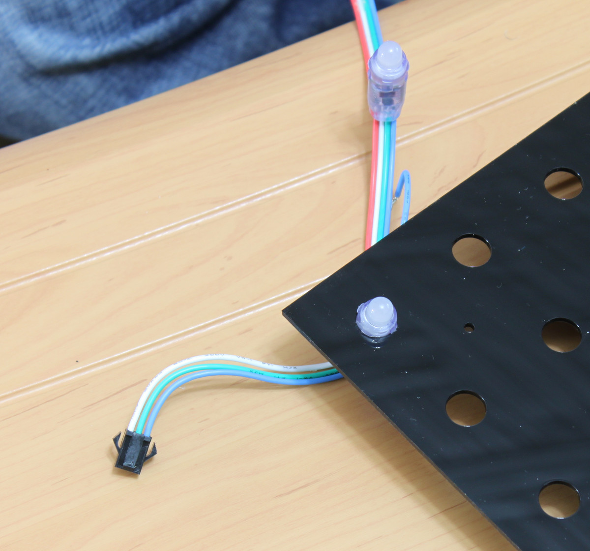
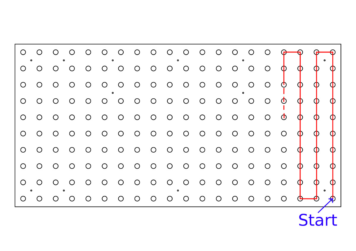
The back and front of the perforated board are different, check the layout of the small mounting holes. The following drawing shows the back of the perforated board. The pixels will be plugged in from this side, such that the heads of the LEDs are on the front. Notice the starting position for the first LED. After inserting the first pixel continue in the alternating pattern as show by the red line.
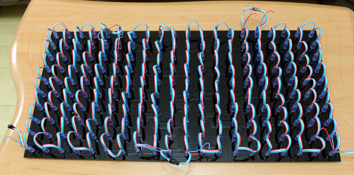
If you finished to attach the first 50 pixels take the next pixels and plug them together with their connectors. Then put the next 50 pixels into the perforated board and repeat this procedure.
Power Supply Cables and Pixel Cables
In the next step we will cut and place the power supply cables. 5m of 2x2.5mm² wires are included in the kit. Cut the following wire lengths from it:
- 1x 95cm
- 1x 80cm
- 1x 55cm
- 1x 40cm
- 1x 20cm
- 1x 10cm
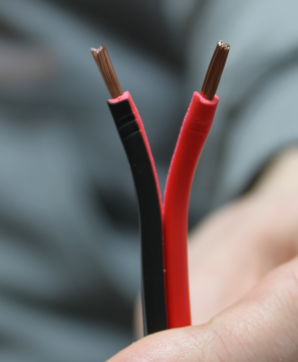
Strip 10mm of the wires on both ends.
Additionally strip 8mm on the power supply wires of the LED pixels (blue and red wires).
Connect the Wires
Pay attention to correctly constructing the power supply wiring. Incorrect wiring can damage the hardware!.
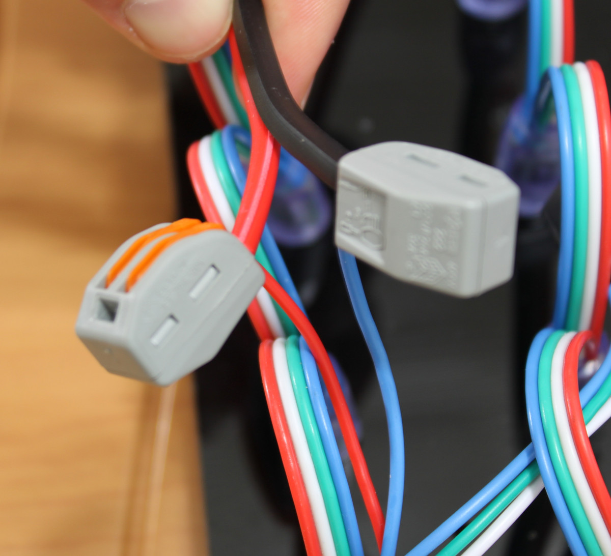
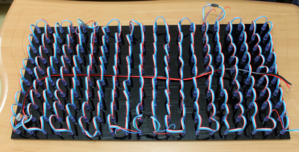
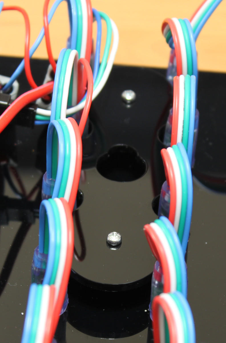
Start the wiring with the 95cm cable. It will connect the later power supply to the last connected LED pixels. Take two 2-wire clamps and connect one to the red LED pixel wire and one on to the blue LED pixel wire. The blue wire will be connected with the black power supply wire. The red wire of the pixels will be connected with the red wire of the power supply. The installed 95cm power supply cable is depicted in the following picture.
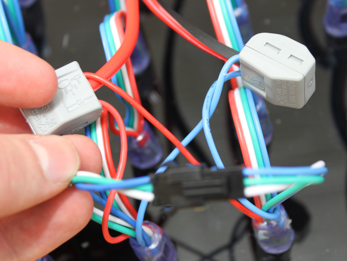
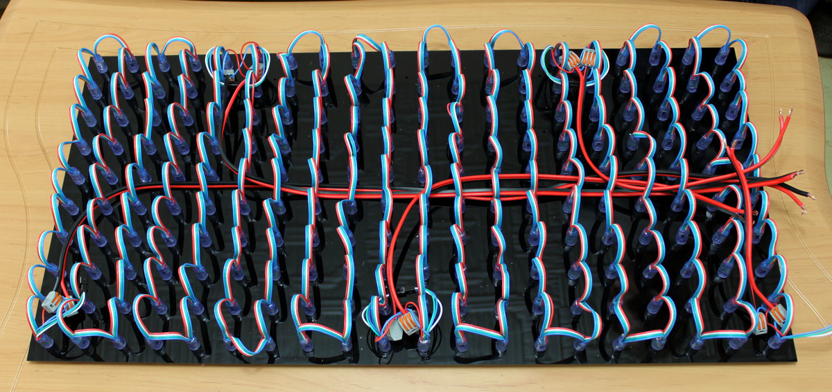
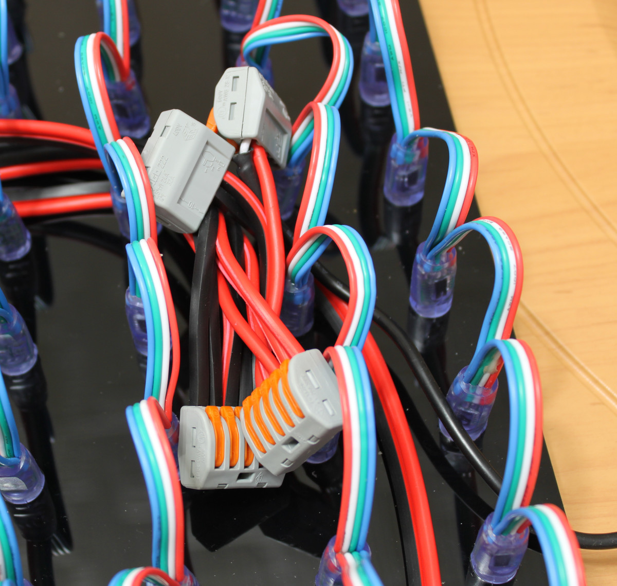
After that wire the 80cm cable. It will be connected to the last but one power supply point. Take two 3-wire clamps and connect the two blue wires of the pixels with the black wire and the two red wires with the red wire. Install it as depicted below.
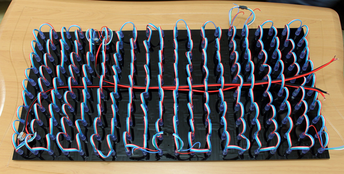
Next we will wire the 55cm cable as before with two 3-wire clamps.
Repeat this step also for the 40cm cable.
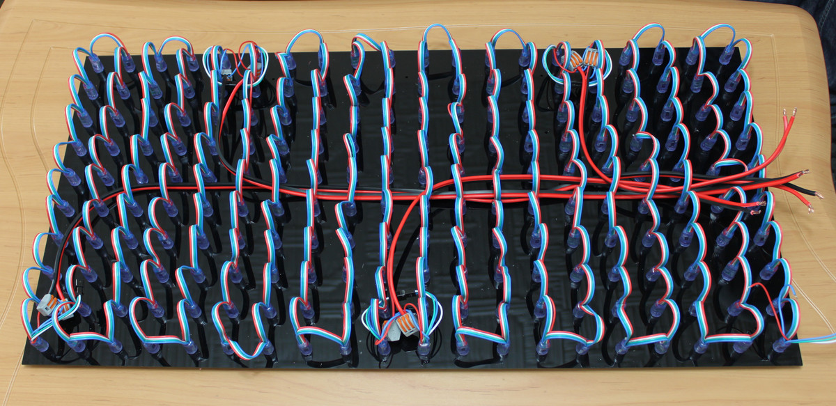
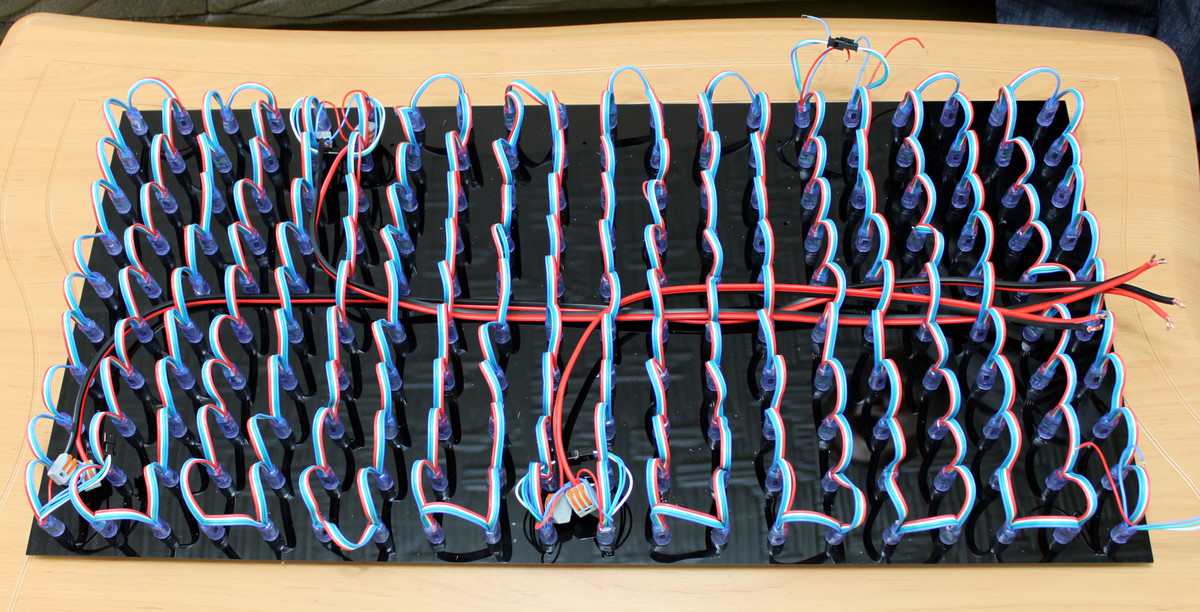
As the last wiring step take two 2-wire clamps and wire the last power supply point with the 20cm cable and install the cable as depicted:
Prepare the 5V Power Supply
Now the wiring of the power cables needs to be joined. Connect the 5V power supply to two 5-wire clamps as depicted below.
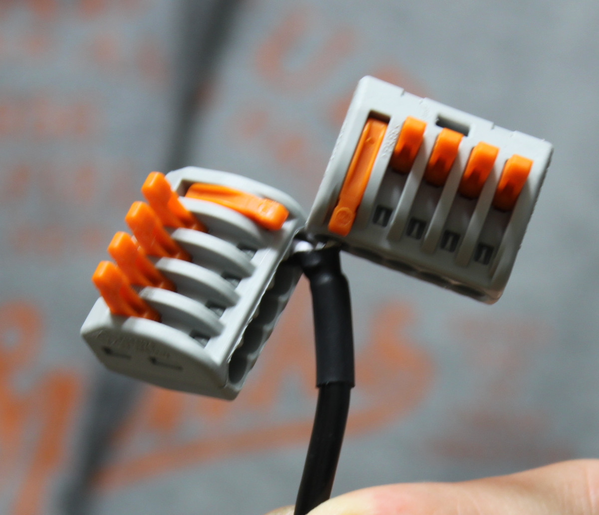
The white wire of the power supply is the 5V wire and will later be connected to the red wires. the black wire is ground and will be connected to the black wires.
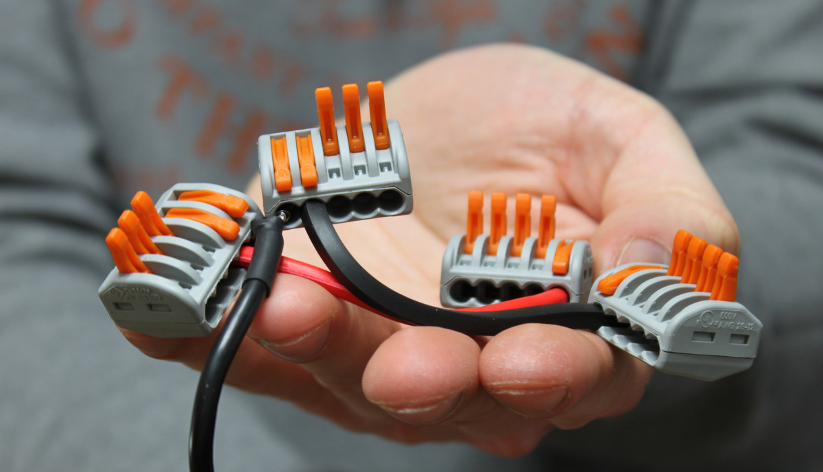
Next take two additional 5-wire clamps and connect these clamps with the previous 5-wire clamps with the 10cm wire.
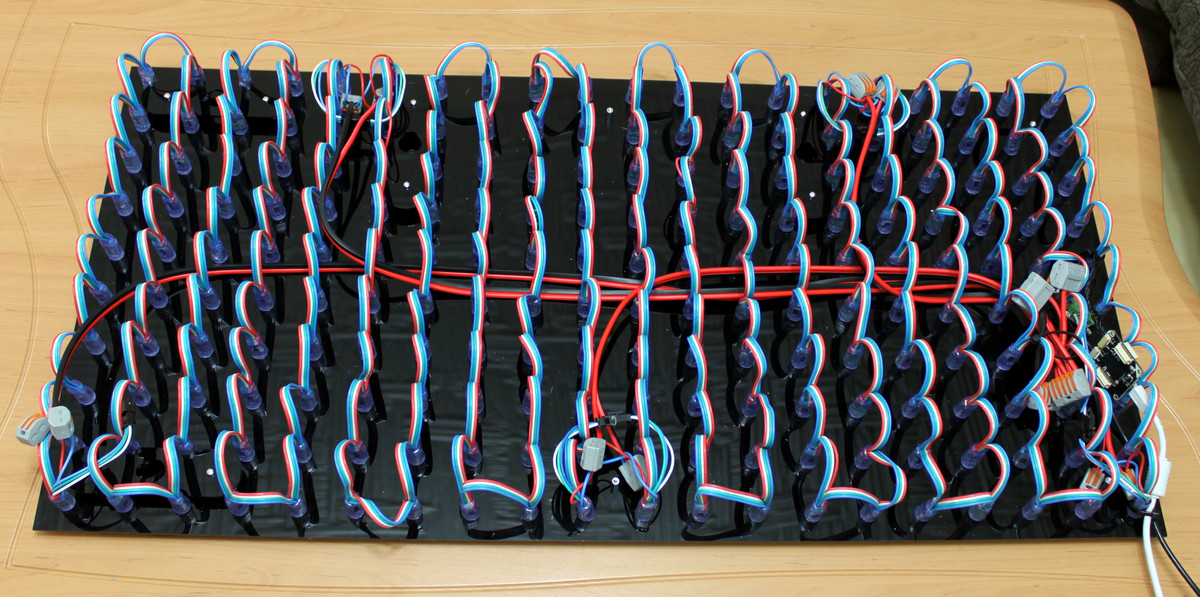
Connect everything
Connect the previously installed power supply cables with the clamps. Install it as depicted in the following picture:
Attach LED Strip Bricklet and Master Brick
After that attach the LED Strip Bricklet and the Master Brick. To do this start by stripping the supplied LED pixel connection wires. 7mm will suffice. Connect it with the Bricklet and install everything as depicted below.
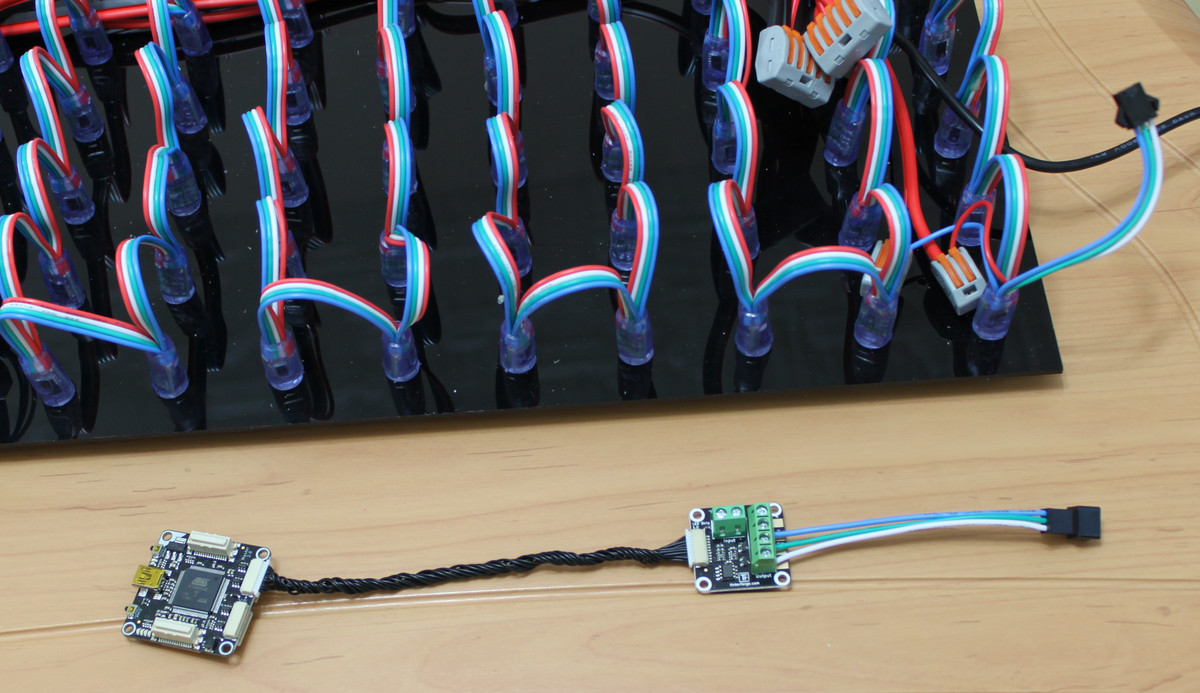
Connect this circuitry with the first pixel and install it as shown below:
Attach Wall Mounting Plates
Attach the wall mounting plates to the perforated board. Use two 10mm spacers (thread inside/inside) and two M3 screws for each mounting plate:
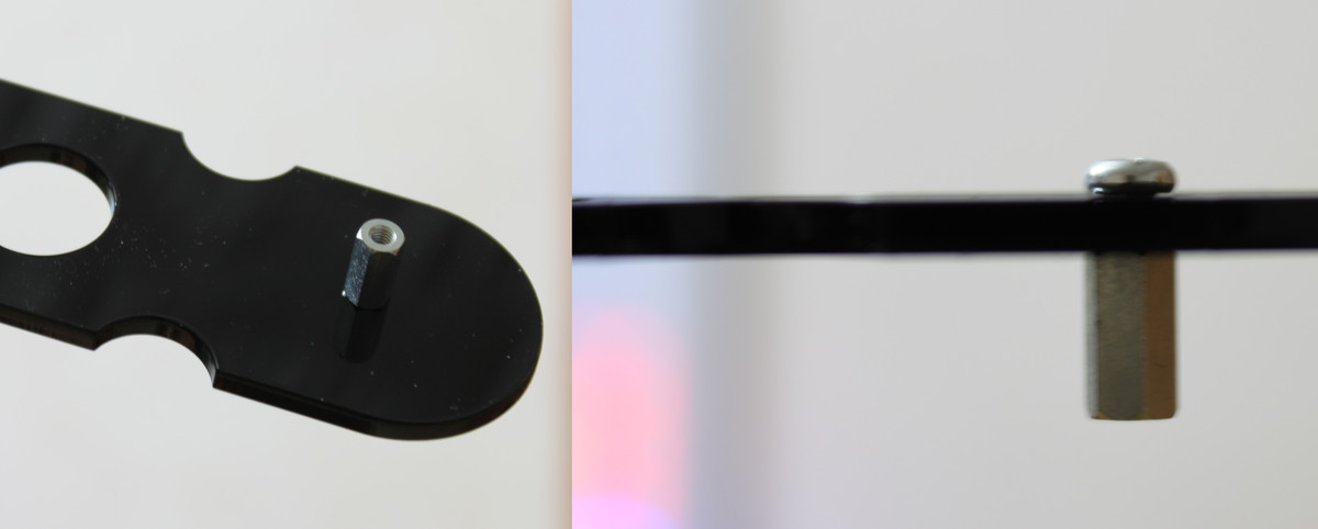
Mount these plates to the back of the perforated board with M3 screws.
After this step the board will look as the following:
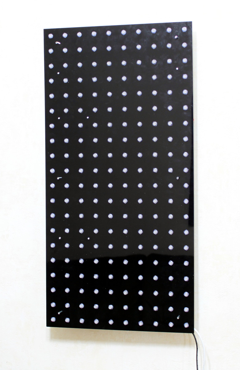
The distance between the mounting holes is 32cm for both, vertical and horizontal mounting.
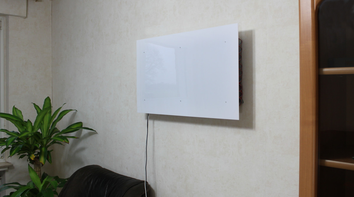
Attach Front Panel (Optional)
This step is optional. You can attach the front panel to the board, dependent on your application you don't have to. The pixels without front panel are very bright.
The following image is from the Tetris example without front panel:
To mount the front panel, add 12mm spacers (thread inside/outside) to six places. Two of this places are blocked by the screws of the wall mounting plates. Just replace these M3 screws with the outside thread of the 12mm spacers. For the other four places the outside thread of the spacer is put in the small holes of the perforated board and locked with a nut.
Now attach the front panel to the six spacers with screws:
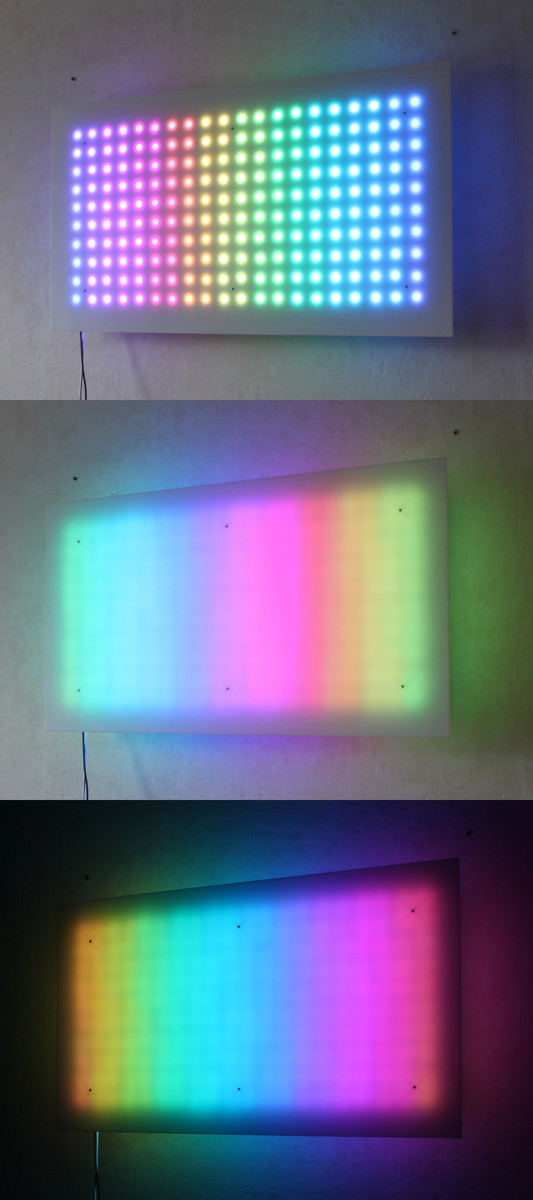
If you want to use the kit to display pixel based things like text or games you can attach the front panel directly to the six 12mm spacers. For diffuse applications like our fire example it is necessary to increase the distance between front panel and the pixels. To do this simply put more spacers between them. In our examples we used two 9mm spacers and one 12mm spacer additionally to the mounted 12mm spacer on each of the six mounting points.
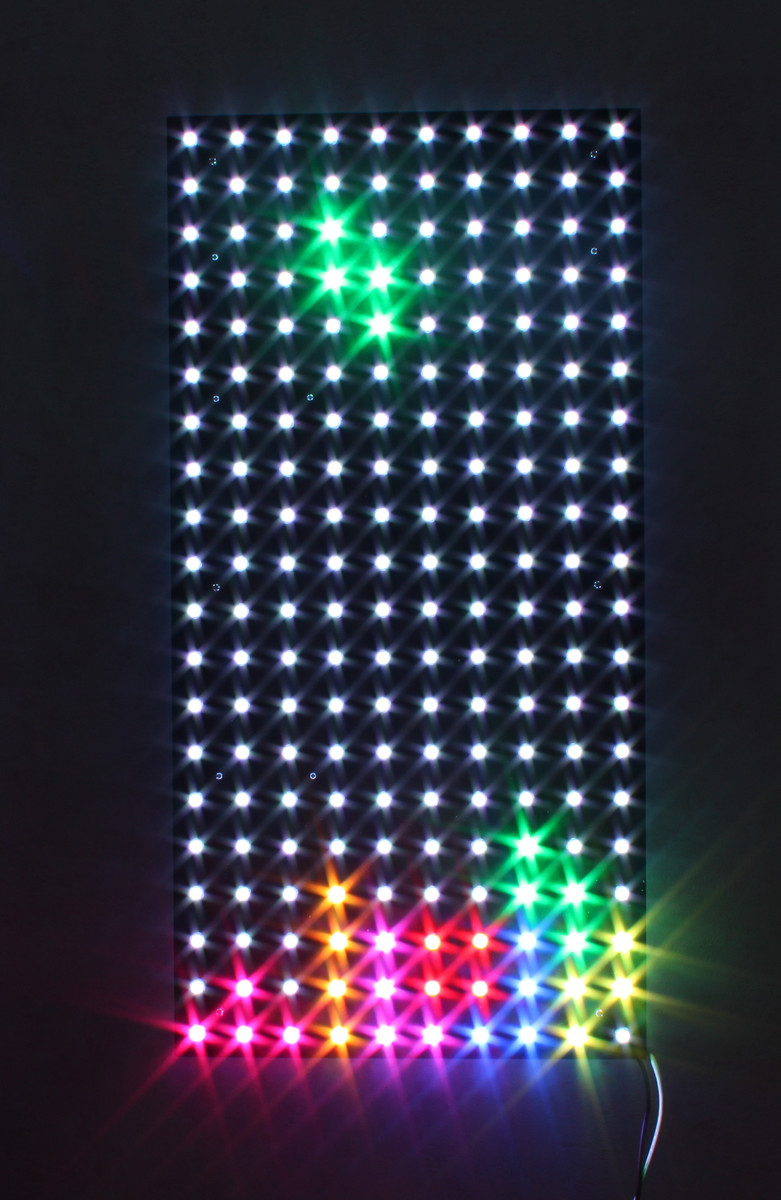
Below you can see the rainbow example with 12mm spacer in daylight, with 2x12mm + 2x9mm spacer in daylight and with 2x12mm + 2x9mm spacer in darkness: