- Getting Started
- Hardware
- Software
- Kits
- Starter Kit: Weather Station
- Starter Kit: Hardware Hacking
- Starter Kit: Server Room Monitoring
- Starter Kit: Server Room Monitoring 2.0
- Starter Kit: Blinkenlights
- Starter Kit: Internet of Things
- Starter Kit: Camera Slider
- Tabletop Weather Station
- Embedded Boards
- Specifications
Hardware Hacking for Beginners
The Starter Kit: Hardware Hacking will encourage you to hack devices and gain some basic knowledge about electronics. In the following you can find a basic description for the supplied hardware.
Basically there are two different purposes for the kit. Each is handled by one specific Bricklet.
Industrial Quad Relay Bricklet
General Description
The Industrial Quad Relay Bricklet consists of four Solid State Relays. Relays are electromechanical driven switches, which means that you can short-circuit a signal controlled by another electrical signal with it. In case of solid state relay the switches are not electromechanical, there are no mechanical parts in it.
If you want to switch something with it, you have to consider the maximum allowed voltage of 30V. Do not try to switch mains voltage directly! In many cases the maximum voltage inside the circuit of a product is given by the voltage of the power supply. For example if you have a battery powered device it is very likely that the maximum voltage in all circuits of this device will not exceed the voltage of the battery. If you have a wall adapter powered device, the maximum voltage will most likely not exceed the output voltage of the wall adapter. Of course there are exceptions. If you are not sure, measure it.
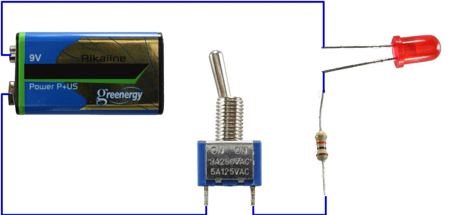
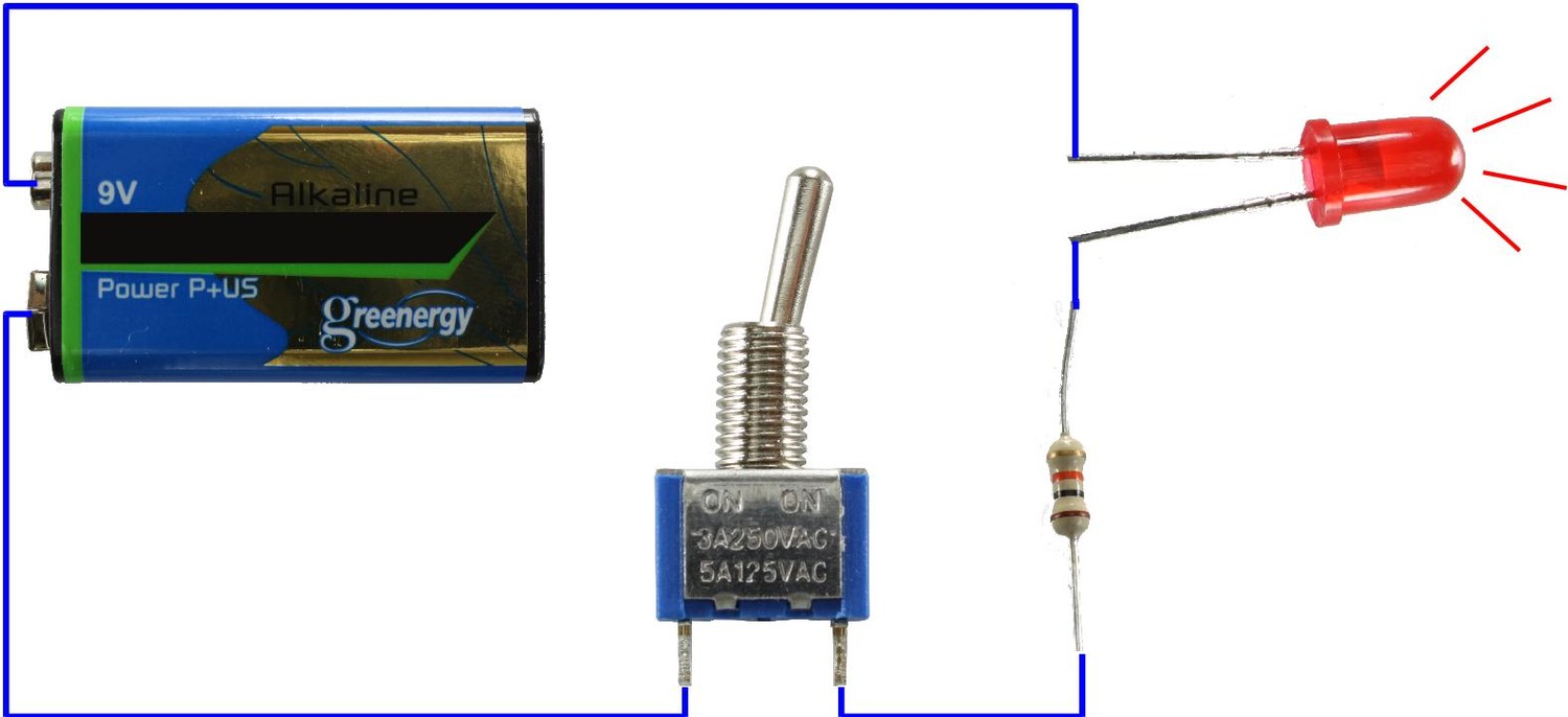
Summary: Typical applications for this Bricklet can be found in switching other circuits on or off. To explain these applications we will start with a simple example. The following schematic depicts a LED (with the typical series resistor) which can be turned on or off depending on the switch.
If we add a second switch in parallel to the first one, the LED will be on if one of the two switches is closed. If both switches are closed the LED will be on, too. If one switch is closed, the other one can not affect the state of the LED. The LED will be on.
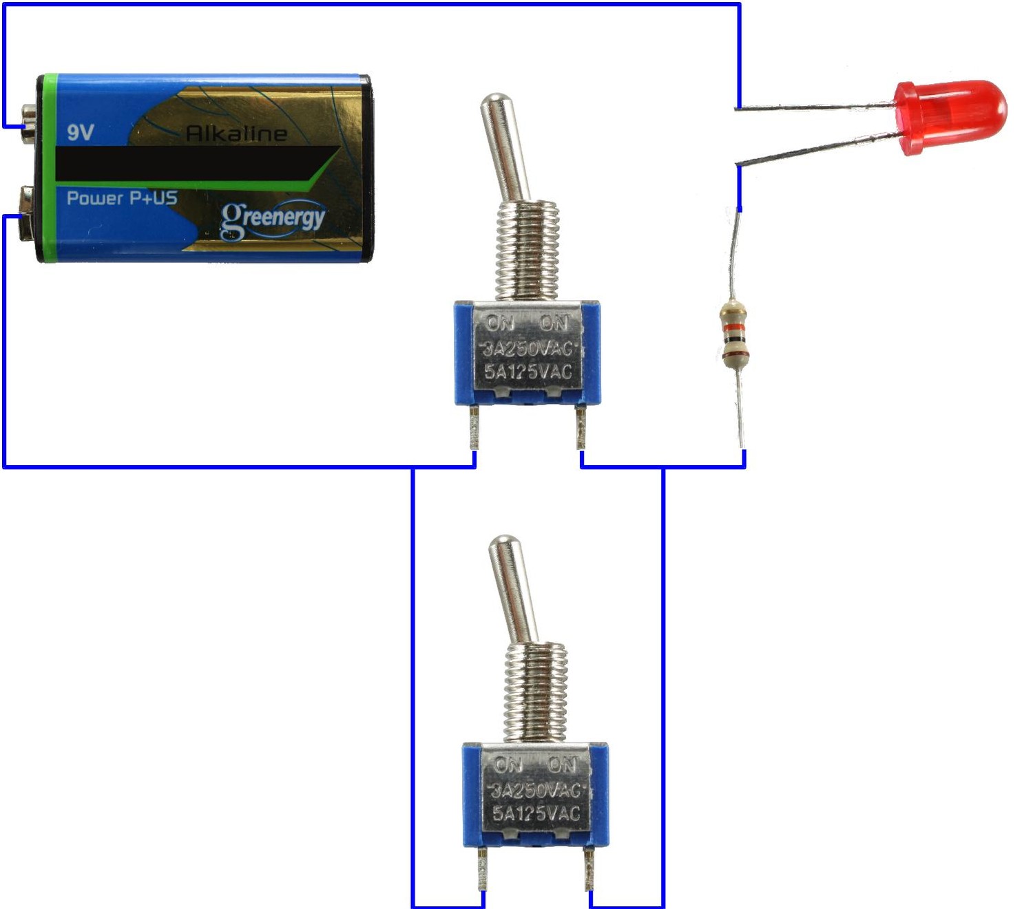
That's the basic idea to make a circuit controllable with an Industrial Quad Relay Bricklet. We simply install a relay of the Bricklet in parallel to an existing switch such that we can bypass it.
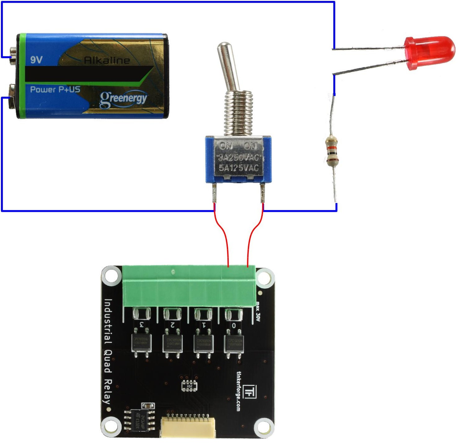
Instead of hacking other devices, you can of course create your own circuits with the Industrial Quad Relay Bricklet.
How to use the Industrial Quad Relay Bricklet?
Let's say you have a device that has buttons to trigger different actions and you want to make them externally triggerable (e.g. remote control). At first you have to take a closer look at the buttons and their connections on the circuit board. In most cases you can directly see two traces of the circuit board connected to the button. If you have identified these connections, which should be shorted-out from the outside, you only have to solder two wires on it (each to one case) and connect one relay of the Industrial Quad Relay Bricklet with it.
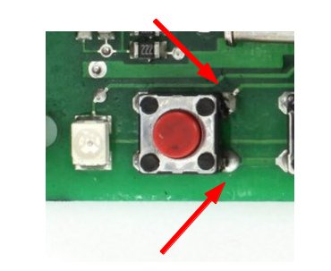
The picture above depicts a button on a circuit board. You can see two traces, one on the top right corner and one on the bottom right corner connected with the button. We have identified the two traces which are shorted by the switch (compare to example circuit above). To make the function of this button externally triggerable you have to solder one wire to the top right and one wire to the bottom right pad of the button. At the end it will look as following:
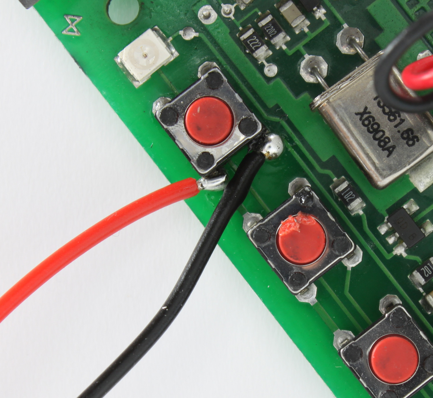
Both wires have to be connected to one port of the Quad Relay Bricklet. Afterwards you are able to trigger the action with the Quad Relay Bricklet that was originally triggered by the button.
Industrial Digital In 4 Bricklet
General Description
The Industrial Digital In 4 Bricklet is equipped with four optocouplers. Technically speaking an optocoupler consists of a LED which triggers a phototransistor with light. This way there is no direct electrical connection between the LED and the phototransistor, the circuit is galvanically isolated.
Less technical speaking the Industrial Digital In 4 Bricklet is equipped with four internal LEDs. If one of these LEDs is on, the respective output will be read out as logical high. If it is off the output will be read out as logical low. The four outputs are connected to the microcontroller of the connected Brick.
If you want to use the Industrial Digital In 4 Bricklet to read out a state of another device you have to connect it to one of the four inputs. This has to be done such that the internal LED will be on if the state to read out is electrically high and will be off if the state is electrically low. Take a look at the electrical description of the Bricklet: Voltages below 2V are interpreted as "low" (LED is off). Voltage above 3V are interpreted as "high" (LED is on). If the voltage is between 2V and 3V it is undefined how the LED will react. Therefore, this voltage range should be avoided.
How to use the Industrial Digital In 4 Bricklet?
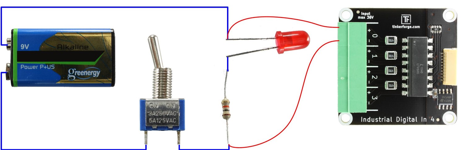
In this example we want to read out the state of a very simple circuit represented by a LED: The LED is switched by some kind of circuitry, in this case a simple manual switch. But it could also be an IC or similar.
To read out the state of the hardware, we can use the state of the LED. To read it out we connect one input of the Industrial Digital In 4 Bricklet to it. Since the minimum high level input voltage is 3V it is not sufficient to connect it to the LED. Typically the (forward-) voltage of an red LED is 1.7V so it is not high enough to trigger a high level on the input port of the Digital In. To solve this we connect the Industrial Digital In 4 Bricklet to the LED and the series resistor. The polarity or, to put it in another way, the way you have connected the wires to the Digital In does not matter. If the Digital In 4 Bricklet does not show any reaction when the LED is triggered, simply swap the wires on the input. The wiring will look as following:
Identify the Series Resistor of a LED
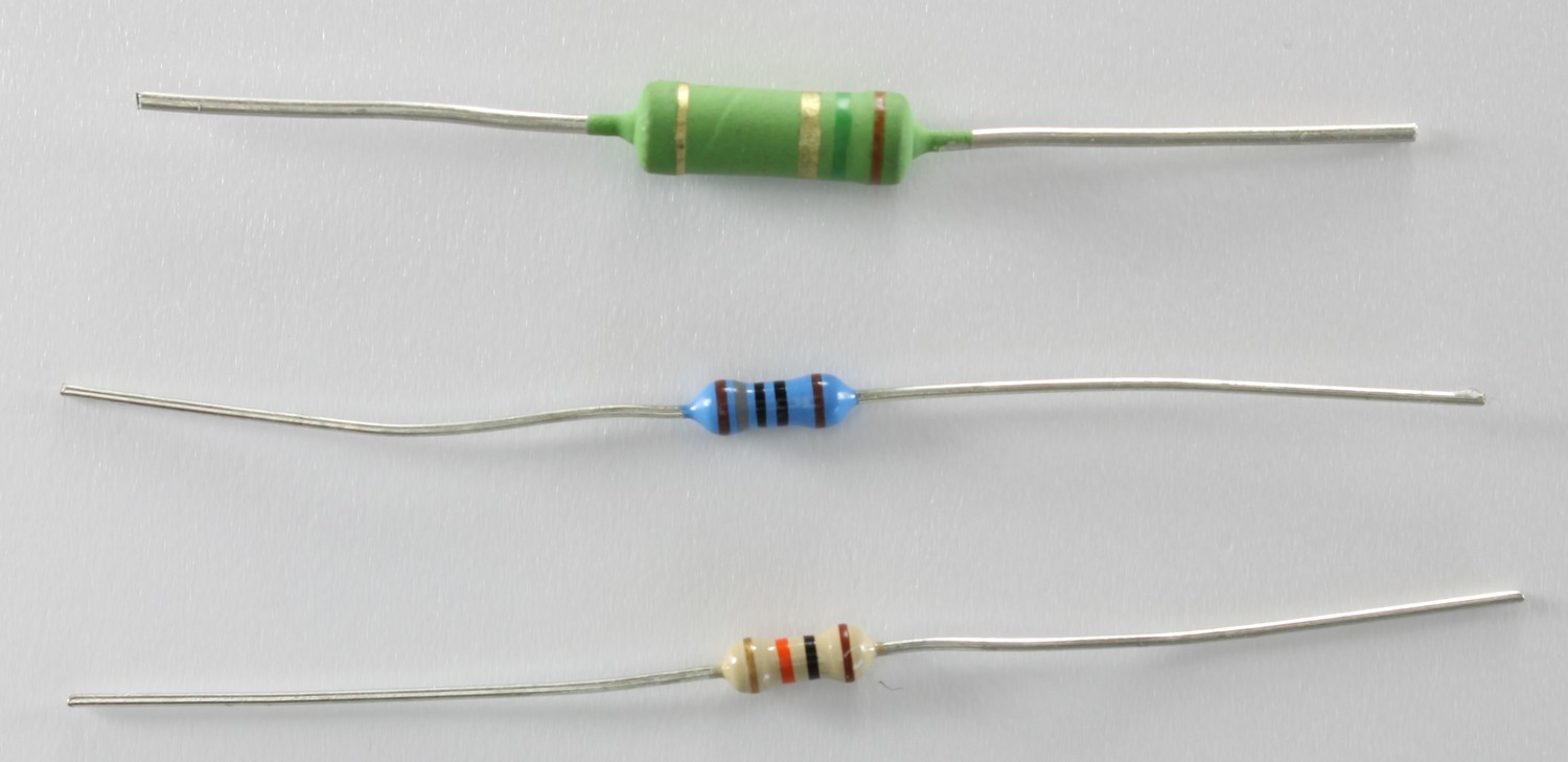
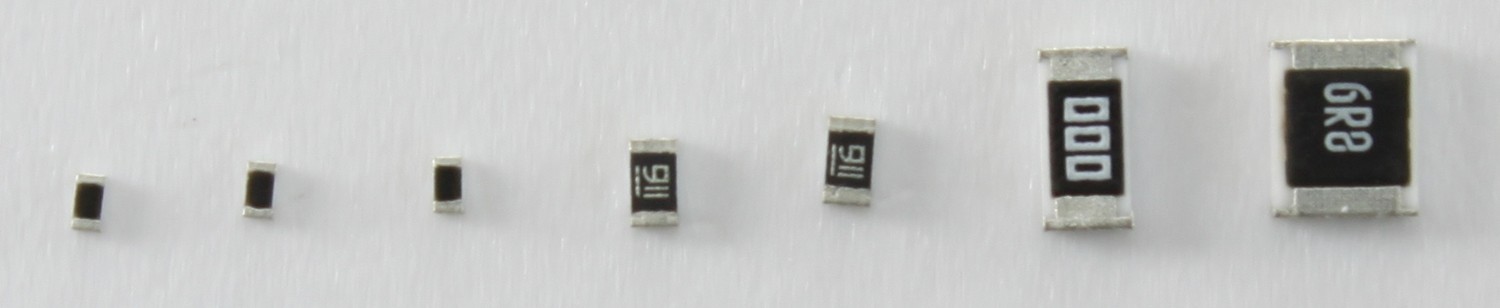
There are many different kinds of resistor packages. The most common are wired packages:
Nowadays many products use so called Surface-Mount Devices (SMD). These devices can differ in their size extremely. There are very tiny devices (e.g. casing 0201: 0.6mm x 0.3mm) or large devices (e.g. casing 2920: 7.4mm x 5.1mm). There are resistors, capacitors, inductances and other devices which can be found directly mounted on the circuit board.
But how to figure out what kind of device it is? There are different options. Experts can tell you which device it may be by looking at its optical features. If the device has a marking it is possible to even identifying the value (e.g. 1k Ohm resistor or 22 Ohm resistor). If there is no marking and it can't be recognized it has to be identified by measuring or by determining its purpose in the circuit.
That's the starting point for this kit. If you like to read out the state of a LED follow the traces until you reach a wired or SMD device. It will most likely be the series resistor.
The next image depicts one example (based on the Control Garage Doors Remotely example).
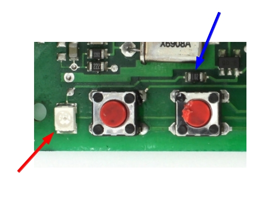
You can see a SMD LED marked with a red arrow. There are two traces connected to this LED. In one trace you can find a small SMD resistor (marked with blue arrow).
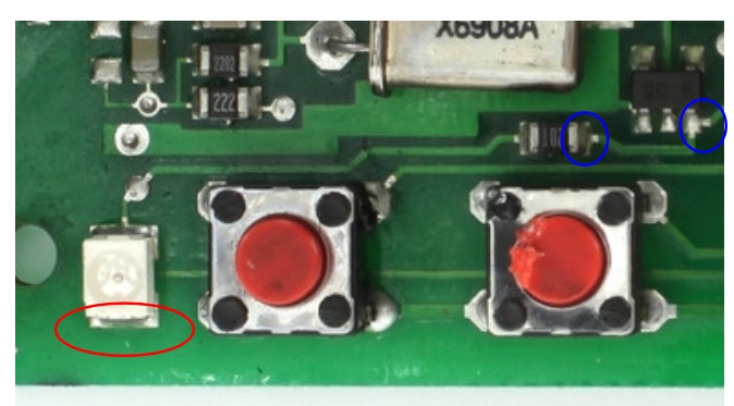
If you want to read out the state of this LED you have to solder one wire directly to the LED (red circle) and one after the series resistor (one of the blue circles). That's it!
Soldering a wire to a solder pad
To solder a wire to a pad, you need a soldering iron and solder.
Don't be afraid if you have never soldered something! For the Starter Kit: Hardware Hacking you only need to solder a wire to a pad.
Soldering a wire to a pad can be done in five basic steps:
Heat the solder pad with the soldering iron.
Add solder to the pad. If it is hot, the solder of the pad will get liquid.
Attach the wire to the pad.
Remove the soldering iron (still hold the wire to the pad).
Wait until solder pad is cooled down.
To make it easier, you can also apply some solder to the stripped part of the wire.
You can find many soldering how-to videos on Youtube.
In our "Starter Kit: Hardware Hacking" how-to video you can also see the process of soldering the wires to the pads (soldering starts at 2:00):