Servo Brick

Note
The Servo Brick is discontinued and is no longer sold. The Servo Bricklet 2.0 is the recommended replacement.
Features
- Controls up to 7 RC Servos with max. 3A over USB
- Brushless motors with external ESC also controllable
- API for many programming languages available
- Supports TurboPWM
- With API adjustable servo voltage, period and pulse width
- Position, velocity and acceleration controllable
- Extendable via two Bricklets ports
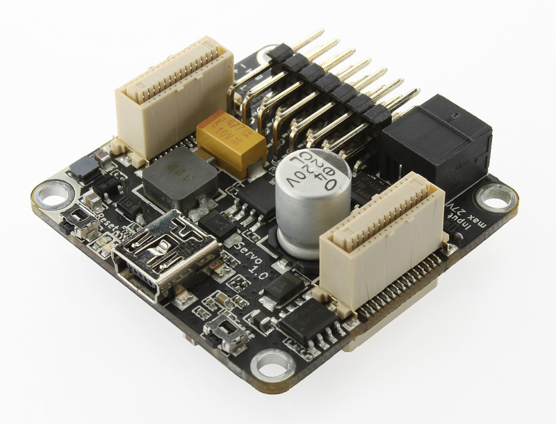
Description
The Servo Brick is able to control up to 7 RC servos with a maximum current of 3A over USB. With the provided API for many programming languages you can control the position, velocity and acceleration of the connected servos. The output voltage is adjustable with API (up to 9V), the drawn current of each servo can be measured independently. Additionally output PWM is configurable for each servo.
Electronic Speed Controllers (ESC) can be connected instead of RC servos. With these, motors e.g Brushless motors, can be controlled. The maximum motor current depends only on the ESC such that it is possible to control motors with 150A or more are.
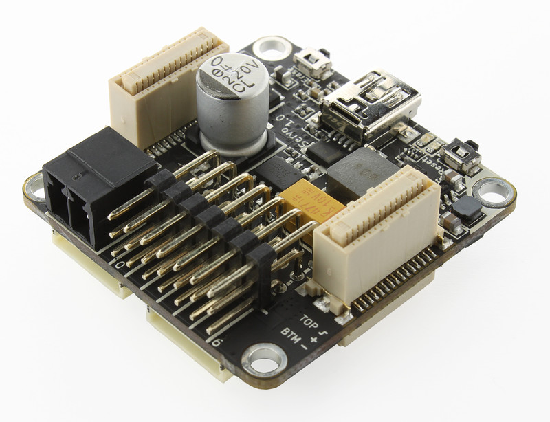
Two Bricklet ports can be used to extend the features of this Brick. It can also be used together with other Bricks in a stack. For example an additional Master Brick with Master Extension allows to replace the USB connection by other cable based (RS485, Ethernet) or wireless (WIFI) connections.
The servos can be powered by an external power supply (black connector) connected directly to the Brick or by the stack internal power supply. If an external power supply is connected the Brick automatically switches to this power supply.
Technical Specifications
| Property | Value |
|---|---|
| Maximum Motor Current (Sum) | 3A |
| Input Voltage | 5V - 25V (at least 1V above configured output voltage) |
| Output Voltage | 2V - 9V (software adjustable) |
| Output Period* | 1µs - 65535µs |
| Pulse Width* | 1µs - 65535µs |
| Velocity* | 0 - 65535 °/100s |
| Acceleration* | 1 - 65535 °/100s² |
| Bricklet Ports | 2 |
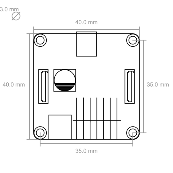
| Dimensions (W x D x H) | 40 x 40 x 16mm (1.57 x 1.57 x 0.63") |
| Weight | 18g |
| Current Consumption | 60mA |
* configurable per servo
Resources
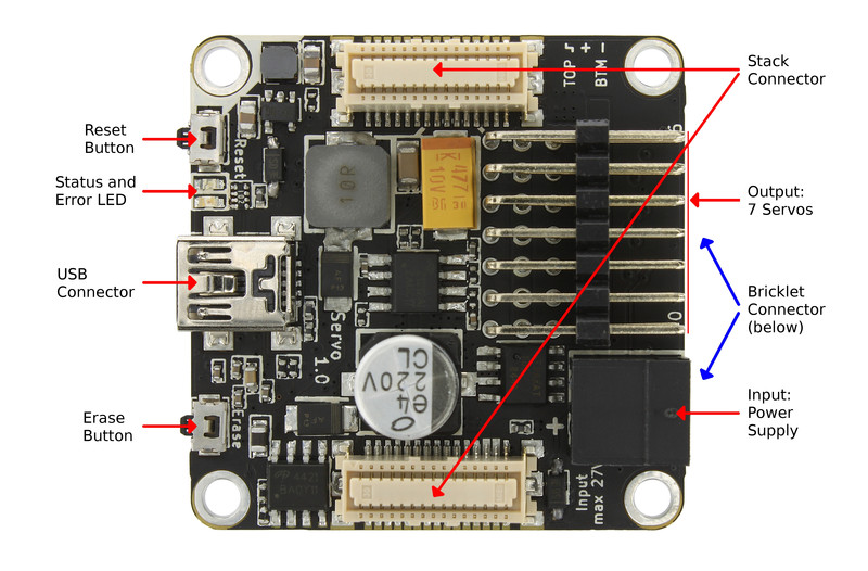
Connectivity
The following picture depicts the different connection possibilities of the Servo Brick.
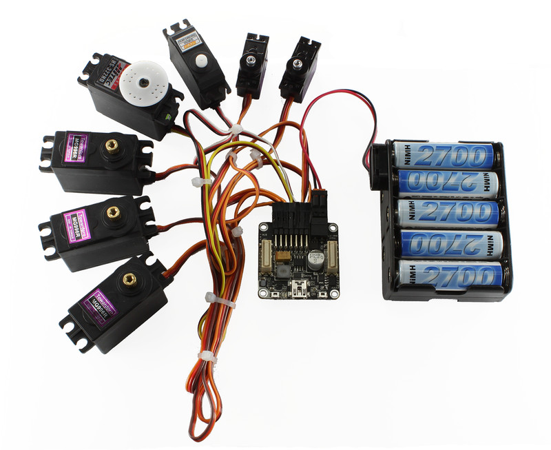
Test your Servo Brick
To test a Servo Brick you need to have Brick Daemon and Brick Viewer installed. Brick Daemon acts as a proxy between the USB interface of the Bricks and the API bindings. Brick Viewer connects to Brick Daemon. It helps to figure out basic information about the connected Bricks and Bricklets and allows to test them.
Connect a RC servo to a port of the Brick and a suitable power supply. Your setup should look as shown below.
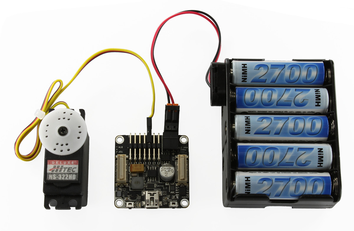
Now connect the Brick to the PC over USB, you should see a new tab named "Servo Brick" in the Brick Viewer after a moment. Select this tab.
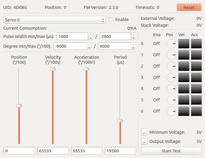
In the left part of the tab you can select the servo to control. You can enable and disable it, configure the PWM pulse width and define the degree range. Additionally you can see the current consumption of the servo. Below there are four sliders to control the position, velocity and acceleration of the servo. The fourth slider can be used to change the period of the PWM (see Configure Servo PWM for more information).
On the right side you can see the external and stack voltage. Below are graphical representations for the state of each servo. Beneath you can configure the minimum input voltage, which allows for undervoltage signals if the voltage is too low. Also you can configure the output voltage.
- ..warning::
- A too high output voltage might damage your servo!
At the bottom right there is a "Start Test" button, which starts a test sequence that performs random movements for each servo.
After this test you can go on with writing your own application. See the Programming Interface section for the API of the Servo Brick and examples in different programming languages.
Configure Servo PWM
Typically you control a RC servo by a PWM signal with a period of 20ms and an on-time of 1ms to 2ms depending on the position you want to achieve. However, some servos do not work properly with these standard settings. Therefore we provide a fully configurable PWM.
The default value for the period is 19.5ms. This period worked on all servos we could get our fingers on (20ms did not work with some of the cheaper Chinese servos). If the datasheet of your servo does specify a preferred period, use it. But it is likely that you don't have to change this value.
More interesting is the minimum and maximum pulse width. The default pulse width is 1ms to 2ms. Most servos can however rotate further when minimum/maximum pulse width is decreased/increased. If your servo comes with a datasheet we recommend to use the values described in there. If you don't have a datasheet you can try to incrementally extend the pulse width until the servo starts to rattle. Use the biggest pulse width that does not produce rattling.
Warning
A wrong PWM configuration for an extended period of time can damage your servo.
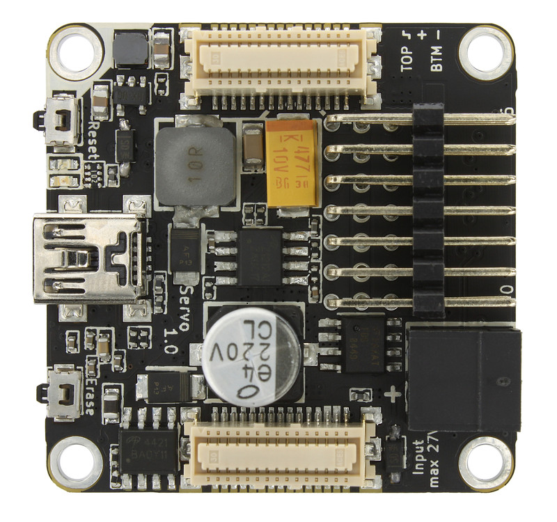
Power Supply
The Servo Brick is equipped with an internal power supply. It offers the possibility to adjust the output voltages for the connected servos. The internal power supply can be powered through the black on-board power-connector or through a Power Supply in a stack. The Servo Brick switches automatically to the on-board power-connector when there is a voltage measured. Since we use a step-down controller for the internal power supply please consider that the input voltage of the Brick has to be 1V higher than the configured output voltage to assure stable operation.
Warning
A too high output voltage can damage your servo.
Usage of ESCs to drive brushless motors
With this Brick you can control up to 7 brushless motors by using external Electronic Speed Controllers (ESC). Simply connect the brushless motor to the ESC and the ESC to the Servo Brick. With this construction the maximum brushless motor current only depends on your selected ESC.
Warning
Many ESCs have a build-in Battery Eliminator Circuits (BEC) which can be used to power RC receivers. If you use a ESC with BEC you have to disable it! Otherwise your ESC or the Brick can be destroyed. To disable BEC you have to remove the red wire from the connector you plug in the Servo Brick (external video tutorial).
Warning
If you use the same power supply for your ESC and the Servo Brick, additionally you have to remove the black (GND) wire too. If you don't remove it, the motor current can flow through the Servo Brick and can destroy the current measurement circuit.
Connect other Hardware
Also other hardware like fan cooler with PWM input can be controlled. These devices must not be powered by the Brick if their voltage is above 9V.
If for example a 12V fan cooler should be controlled it should not be powered by the Brick! Otherwise voltage peaks, caused by the fan, can lead to a exploding tantal capacitor on the brick (max. capacitor voltage 10V). To prevent this the fan should be powered externally by 12V (12V, ground). The PWM line will be connected to the Brick. Additionally ground has to be connected to the Brick, too.
Error LED
The red LED is enabled so long as the input voltage is below the user configurable minimum voltage.
Programming Interface
See Programming Interface for a detailed description.
| Language | API | Examples | Installation |
|---|---|---|---|
| C/C++ | API | Examples | Installation |
| C# | API | Examples | Installation |
| Delphi/Lazarus | API | Examples | Installation |
| Go | API | Examples | Installation |
| Java | API | Examples | Installation |
| JavaScript | API | Examples | Installation |
| LabVIEW | API | Examples | Installation |
| Mathematica | API | Examples | Installation |
| MATLAB/Octave | API | Examples | Installation |
| MQTT | API | Examples | Installation |
| openHAB | API | Examples | Installation |
| Perl | API | Examples | Installation |
| PHP | API | Examples | Installation |
| Python | API | Examples | Installation |
| Ruby | API | Examples | Installation |
| Rust | API | Examples | Installation |
| Shell | API | Examples | Installation |
| Visual Basic .NET | API | Examples | Installation |
| TCP/IP | API | ||
| Modbus | API |
FAQ
My servos are shaking, help!
The reason for this is typically a voltage drop, caused by repeated high current peaks produced by the connected servos. First you should check the input voltage, it should be at least 1V higher then the configured output voltage.
Typically this problem occurs when the power supply can't handle the high current peaks. To test if your power supply is the problem, you can try batteries. Batteries normally don't have problems with current peaks.
If you are using batteries and the problem is still occurring, check the voltage of the batteries when the servos are in use. If your batteries are too weak, the voltage is dropping (in this case use full batteries).
If your servos only start shaking when you reach the maximum/minimum angle, you have configured a too high/low pulse width. In this case you have to reduce the pulse width, otherwise your servos might get damaged over time.