- Getting Started
- Hardware
- Bricks
- Bricklets
- Accelerometer Bricklet 2.0
- Air Quality Bricklet
- Ambient Light Bricklet 3.0
- Analog In Bricklet 3.0
- Analog Out Bricklet 2.0
- Analog Out Bricklet 3.0
- Barometer Bricklet
- Barometer Bricklet 2.0
- Breakout Bricklet
- CAN Bricklet
- CAN Bricklet 2.0
- CO2 Bricklet 2.0
- Color Bricklet
- Color Bricklet 2.0
- Compass Bricklet
- DC Bricklet 2.0
- Distance IR Bricklet
- Distance IR Bricklet 2.0
- Distance US Bricklet 2.0
- DMX Bricklet
- Dual Button Bricklet 2.0
- Dust Detector Bricklet
- E-Paper 296x128 Bricklet
- Energy Monitor Bricklet
- GPS Bricklet 2.0
- GPS Bricklet 3.0
- Hall Effect Bricklet
- Hall Effect Bricklet 2.0
- Humidity Bricklet 2.0
- IMU Bricklet 3.0
- Industrial Analog Out Bricklet 2.0
- Industrial Counter Bricklet
- Industrial Digital In 4 Bricklet 2.0
- Industrial Digital Out 4 Bricklet
- Industrial Digital Out 4 Bricklet 2.0
- Industrial Dual 0-20mA Bricklet
- Industrial Dual 0-20mA Bricklet 2.0
- Industrial Dual AC Relay Bricklet
- Industrial Dual Analog In Bricklet 2.0
- Industrial Dual Relay Bricklet
- Industrial PTC Bricklet
- Industrial Quad Relay Bricklet 2.0
- IO-16 Bricklet
- IO-16 Bricklet 2.0
- IO-4 Bricklet 2.0
- Isolator Bricklet
- Joystick Bricklet
- Joystick Bricklet 2.0
- Laser Range Finder Bricklet 2.0
- LCD 128x64 Bricklet
- LCD 20x4 Bricklet
- LED Strip Bricklet 2.0
- Line Bricklet
- Linear Poti Bricklet
- Linear Poti Bricklet 2.0
- Load Cell Bricklet 2.0
- Motion Detector Bricklet 2.0
- Motorized Linear Poti Bricklet
- Multi Touch Bricklet
- Multi Touch Bricklet 2.0
- NFC Bricklet
- OLED 128x64 Bricklet 2.0
- OLED 64x48 Bricklet
- One Wire Bricklet
- Outdoor Weather Bricklet
- Particulate Matter Bricklet
- Performance DC Bricklet
- Piezo Speaker Bricklet
- Piezo Speaker Bricklet 2.0
- Real-Time Clock Bricklet
- Real-Time Clock Bricklet 2.0
- Remote Switch Bricklet 2.0
- RGB LED Bricklet 2.0
- RGB LED Button Bricklet
- Rotary Encoder Bricklet 2.0
- Rotary Poti Bricklet
- Rotary Poti Bricklet 2.0
- RS232 Bricklet
- RS232 Bricklet 2.0
- RS485 Bricklet
- Segment Display 4x7 Bricklet
- Segment Display 4x7 Bricklet 2.0
- Servo Bricklet 2.0
- Silent Stepper Bricklet 2.0
- Solid State Relay Bricklet 2.0
- Sound Intensity Bricklet
- Sound Pressure Level Bricklet
- Temperature Bricklet
- Temperature Bricklet 2.0
- Temperature IR Bricklet 2.0
- Thermal Imaging Bricklet
- Thermocouple Bricklet 2.0
- Tilt Bricklet
- UV Light Bricklet 2.0
- Voltage/Current Bricklet 2.0
- XMC1400 Breakout Bricklet
- Master Extensions
- Power Supplies
- Discontinued Products
- Timeline
- Software
- Kits
- Embedded Boards
- Specifications
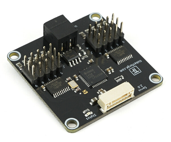
Servo Bricklet 2.0


Features
- Controls up to 10 RC Servos
- Brushless motors with external ESC also controllable
- Adjustable Period and pulse width
- Uses motion planning to reach position with smooth motion
- Velocity and acceleration/deceleration can be configured
- Current measurement for each individual channel
Description
The Servo Bricklet is able to control up to 10 RC servos. With the provided API for many programming languages you can control the position, velocity and acceleration/deceleration of the connected servos. Motion planning is used to reach a position with smooth motion. The current-draw of each servo can be measured independently. Additionally output PWM (pulse width and period) is configurable for each servo.
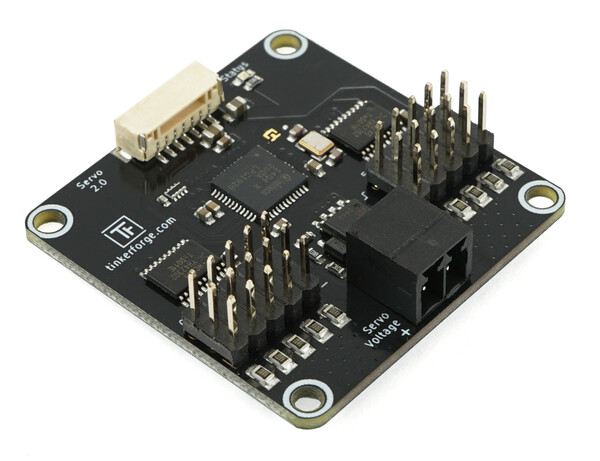
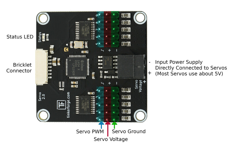
The servos are powered by an external power supply (black connector). The voltage from this connector is directly connected to the servos.
Technical Specifications
| Property | Value |
|---|---|
| Current Consumption | 75mW (15mA at 5V) |
| Input Voltage | 5V-24V (is directly supplied to servo/fan) |
| Output Period* | 1µs - 65535µs |
| Pulse Width* | 1µs - 65535µs |
| Velocity* | 0 - 500000 °/100s |
| Acceleration* | 0 - 500000 °/100s² |
| Deceleration* | 0 - 500000 °/100s² |
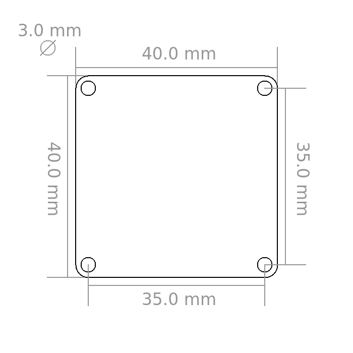
| Dimensions (W x D x H) | 40 x 40 x 10mm (1.57 x 1.57 x 0.39") |
| Weight | 9g |
* configurable per servo channel
Resources
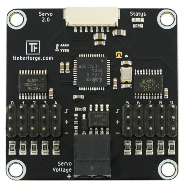
Connectivity
The following picture depicts the different connection possibilities of the Servo Bricklet 2.0.
Test your Servo Bricklet 2.0
To test a Servo Bricklet 2.0 you need to have Brick Daemon and Brick Viewer installed. Brick Daemon acts as a proxy between the USB interface of the Bricks and the API bindings. Brick Viewer connects to Brick Daemon. It helps to figure out basic information about the connected Bricks and Bricklets and allows to test them.
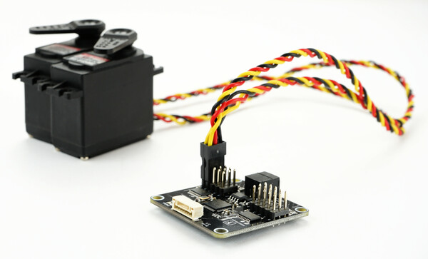
Connect a RC servo to a port of the Brick and a suitable power supply.
If you connect the Brick to the PC over USB, you should see a new tab named "Servo Bricklet 2.0" in the Brick Viewer after a moment. Select this tab.
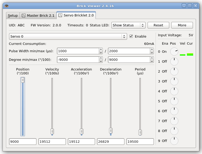
In the left part of the tab you can select the servo to control. You can enable and disable it, configure the PWM pulse width and define the degree range. Additionally you can see the current consumption of the servo. Below there are four sliders to control the position, velocity and acceleration of the servo. The fourth slider can be used to change the period of the PWM (see Configure Servo PWM for more information).
On the right side you can see the input voltage. Below are graphical representations for the state of each servo.
After this test you can go on with writing your own application. See the Programming Interface section for the API of the Servo Bricklet 2.0 and examples in different programming languages.
Configure Servo PWM
Typically you control a RC servo by a PWM signal with a period of 20ms and an on-time of 1ms to 2ms depending on the position you want to achieve. However, some servos do not work properly with these standard settings. Therefore we provide a fully configurable PWM.
The default value for the period is 19.5ms. This period worked on all servos we could get our fingers on (20ms did not work with some of the cheaper Chinese servos). If the datasheet of your servo does specify a preferred period, use it. But it is likely that you don't have to change this value.
More interesting is the minimum and maximum pulse width. The default pulse width is 1ms to 2ms. Most servos can however rotate further when minimum/maximum pulse width is decreased/increased. If your servo comes with a datasheet we recommend to use the values described in there. If you don't have a datasheet you can try to incrementally extend the pulse width until the servo starts to rattle. Use the biggest pulse width that does not produce rattling.
Warning
A wrong PWM configuration for an extended period of time can damage your servo.
Usage of ESCs to drive brushless motors
With this Brick you can control up to 10 brushless motors by using external Electronic Speed Controllers (ESC). Simply connect the brushless motor to the ESC and the ESC to the Servo Brick. With this construction the maximum brushless motor current only depends on your selected ESC.
Warning
Many ESCs have a build-in Battery Eliminator Circuits (BEC) which can be used to power RC receivers. If you use a ESC with BEC you have to disable it! Otherwise your ESC or the Brick can be destroyed. To disable BEC you have to remove the red wire from the connector you plug in the Servo Brick (external video tutorial).
Warning
If you use the same power supply for your ESC and the Servo Brick, additionally you have to remove the black (GND) wire too. If you don't remove it, the motor current can flow through the Servo Brick and can destroy the current measurement circuit.
Connect other Hardware
Also other hardware like fan cooler with PWM input can be controlled.
You can use 12V fans or 24V fans and connect the 12V/24V to to the black input voltage connector. The control PWM input of the fan must however accept 0V low level und 5V high level. The majority of 12V/24V PWM controllable fans work this way, but check the datasheet of of the fan before you connect it.
Coming Soon: Image/Video + example configuration
Case
TBD
Programming Interface
See Programming Interface for a detailed description.
| Language | API | Examples | Installation |
|---|---|---|---|
| C/C++ | API | Examples | Installation |
| C/C++ for Microcontrollers | API | Examples | Installation |
| C# | API | Examples | Installation |
| Delphi/Lazarus | API | Examples | Installation |
| Go | API | Examples | Installation |
| Java | API | Examples | Installation |
| JavaScript | API | Examples | Installation |
| LabVIEW | API | Installation | |
| Mathematica | API | Examples | Installation |
| MATLAB/Octave | API | Examples | Installation |
| MQTT | API | Examples | Installation |
| Perl | API | Examples | Installation |
| PHP | API | Examples | Installation |
| Python | API | Examples | Installation |
| Ruby | API | Examples | Installation |
| Rust | API | Examples | Installation |
| Shell | API | Examples | Installation |
| Visual Basic .NET | API | Examples | Installation |
| TCP/IP | API | ||
| Modbus | API |
FAQ
My servos are shaking, help!
The reason for this is typically a voltage drop, caused by repeated high current peaks produced by the connected servos. First you should check the input voltage, it should be at least 1V higher then the configured output voltage.
Typically this problem occurs when the power supply can't handle the high current peaks. To test if your power supply is the problem, you can try batteries. Batteries normally don't have problems with current peaks.
If you are using batteries and the problem is still occurring, check the voltage of the batteries when the servos are in use. If your batteries are too weak, the voltage is dropping (in this case use full batteries).
If your servos only start shaking when you reach the maximum/minimum angle, you have configured a too high/low pulse width. In this case you have to reduce the pulse width, otherwise your servos might get damaged over time.