- Getting Started
- Hardware
- Bricks
- Bricklets
- Accelerometer Bricklet 2.0
- Air Quality Bricklet
- Ambient Light Bricklet 3.0
- Analog In Bricklet 3.0
- Analog Out Bricklet 2.0
- Analog Out Bricklet 3.0
- Barometer Bricklet
- Barometer Bricklet 2.0
- Breakout Bricklet
- CAN Bricklet
- CAN Bricklet 2.0
- CO2 Bricklet 2.0
- Color Bricklet
- Color Bricklet 2.0
- Compass Bricklet
- DC Bricklet 2.0
- Distance IR Bricklet
- Distance IR Bricklet 2.0
- Distance US Bricklet 2.0
- DMX Bricklet
- Dual Button Bricklet 2.0
- Dust Detector Bricklet
- E-Paper 296x128 Bricklet
- Energy Monitor Bricklet
- GPS Bricklet 2.0
- GPS Bricklet 3.0
- Hall Effect Bricklet
- Hall Effect Bricklet 2.0
- Humidity Bricklet 2.0
- IMU Bricklet 3.0
- Industrial Analog Out Bricklet 2.0
- Industrial Counter Bricklet
- Industrial Digital In 4 Bricklet 2.0
- Industrial Digital Out 4 Bricklet
- Industrial Digital Out 4 Bricklet 2.0
- Industrial Dual 0-20mA Bricklet
- Industrial Dual 0-20mA Bricklet 2.0
- Industrial Dual AC Relay Bricklet
- Industrial Dual Analog In Bricklet 2.0
- Industrial Dual Relay Bricklet
- Industrial PTC Bricklet
- Industrial Quad Relay Bricklet 2.0
- IO-16 Bricklet
- IO-16 Bricklet 2.0
- IO-4 Bricklet 2.0
- Isolator Bricklet
- Joystick Bricklet
- Joystick Bricklet 2.0
- Laser Range Finder Bricklet 2.0
- LCD 128x64 Bricklet
- LCD 20x4 Bricklet
- LED Strip Bricklet 2.0
- Line Bricklet
- Linear Poti Bricklet
- Linear Poti Bricklet 2.0
- Load Cell Bricklet 2.0
- Motion Detector Bricklet 2.0
- Motorized Linear Poti Bricklet
- Multi Touch Bricklet
- Multi Touch Bricklet 2.0
- NFC Bricklet
- OLED 128x64 Bricklet 2.0
- OLED 64x48 Bricklet
- One Wire Bricklet
- Outdoor Weather Bricklet
- Particulate Matter Bricklet
- Performance DC Bricklet
- Piezo Speaker Bricklet
- Piezo Speaker Bricklet 2.0
- Real-Time Clock Bricklet
- Real-Time Clock Bricklet 2.0
- Remote Switch Bricklet 2.0
- RGB LED Bricklet 2.0
- RGB LED Button Bricklet
- Rotary Encoder Bricklet 2.0
- Rotary Poti Bricklet
- Rotary Poti Bricklet 2.0
- RS232 Bricklet
- RS232 Bricklet 2.0
- RS485 Bricklet
- Segment Display 4x7 Bricklet
- Segment Display 4x7 Bricklet 2.0
- Servo Bricklet 2.0
- Silent Stepper Bricklet 2.0
- Solid State Relay Bricklet 2.0
- Sound Intensity Bricklet
- Sound Pressure Level Bricklet
- Temperature Bricklet
- Temperature Bricklet 2.0
- Temperature IR Bricklet 2.0
- Thermal Imaging Bricklet
- Thermocouple Bricklet 2.0
- Tilt Bricklet
- UV Light Bricklet 2.0
- Voltage/Current Bricklet 2.0
- XMC1400 Breakout Bricklet
- Master Extensions
- Power Supplies
- Discontinued Products
- Timeline
- Software
- Kits
- Embedded Boards
- Specifications
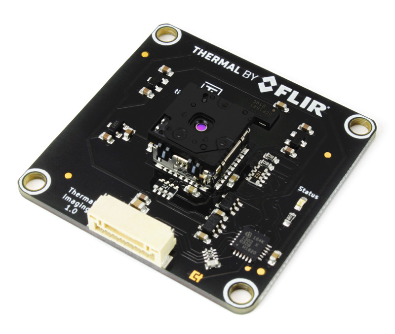
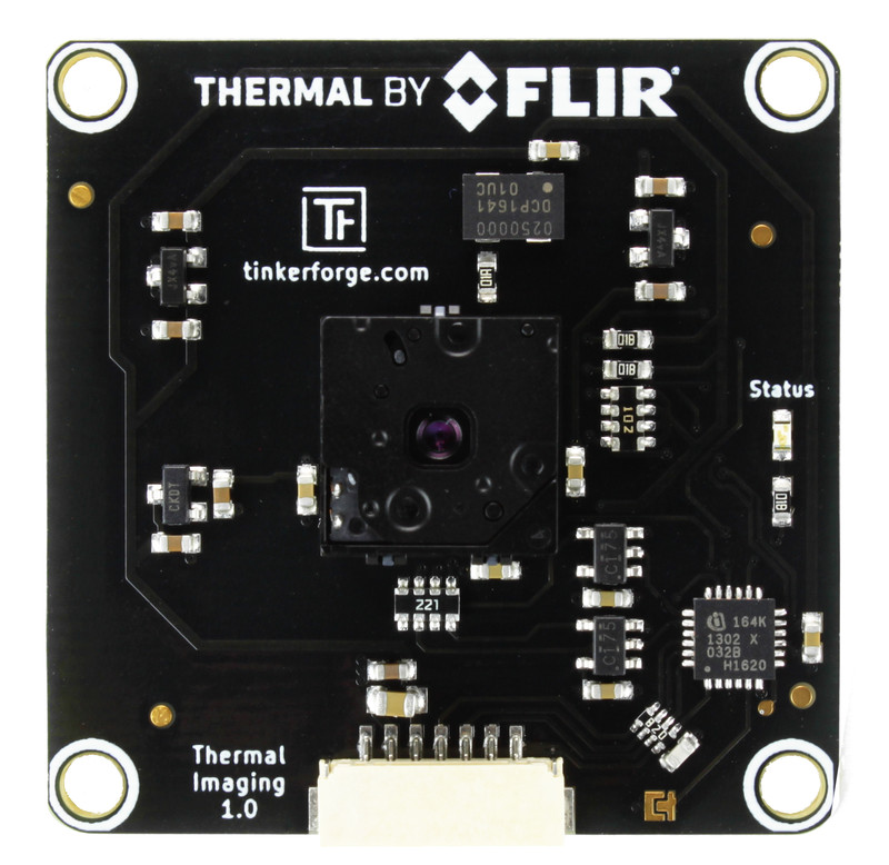
Thermal Imaging Bricklet

Features
- 80x60 pixel thermal imaging camera
- Measurement range -10°C to 450°C
- Uses FLIR Lepton with radiometry and shutter
- High Contrast Image with 8.6Hz and 8 bit resolution (for display)
- Temperature Image with 4.5Hz and 16 bit resolution (for scientific calculations)
- Definable spotmeter with min, max, mean temperature measurement
- Automatic shutter control
Description
The Thermal Imaging Bricklet is equipped with a 80x60 pixel thermal imaging camera. It can be connected to a Brick.
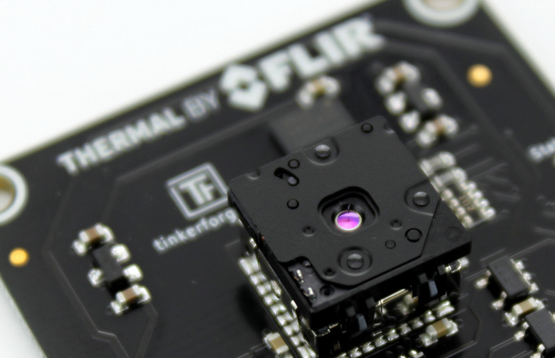
The Bricklet uses a FLIR Lepton sensor with radiometry and shutter. It can measure a temperature range of -10°C up to 450°C with a resolution of 80x60 pixel.
A spotmeter can be set to measure the minimum, mean and maximum temperature of a user defined region in the image.
The Bricklet supports two image modes: High Contrast Image and Temperature Image.
In High Contrast Image mode the Bricklet provides an image stream with 8.6Hz and 8 bit resolution. The image data is gray-scale, the high dynamic range of the sensor is collapsed to be appropriate for display. This mode is used in thermal imaging cameras that are available on the market. Typically the gray-scale data is converted in a pseudo-color image by a lookup table.
In Temperature Image mode the Bricklet provides an image stream with 4.5Hz and 16 bit resolution. In the image data each pixel represents one 16 bit temperature value between -10°C and 450°C with a resolution of 0.1°C or a value between -10°C and 140°C with a resolution of 0.01°C (depending on the resolution configuration). This mode can be used for scientific calculations and to analyze absolute temperature changes.
The shutter is automatically controlled by the Bricklet.
Technical Specifications
| Property | Value |
|---|---|
| Current Consumption | 546mW (109.2mA at 5V, running) |
| Resolution | 80x60 |
| Frame Rate | 8.6Hz (High Contrast Image), 4.5Hz (Temperature Image) |
| Field of View | 51° horizontal, 66° diagonal |
| Depth of Field | 10cm to infinity |
| Thermal Sensitivity | < 50mK (0.05°C) |
| Radiometric accuracy | ±5°C or 5% (typical) |
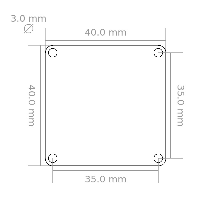
| Dimensions (W x D x H) | 40 x 40 x 9mm (1.57 x 1.57 x 0.35") |
| Weight | 8g |
Resources
Demo Video
In the following video you can see the Thermal Imaging Bricklet in action. We film a kitchen sink with a warm cup of coffee. Then we turn warm water on and then change from to cold and back to warm.
You can see that first the cup of coffee is the warmest object in the frame. The water slowly gets warmer then the coffee after we turn on the tap. When we turn the tap to cold it gets colder again.
You can also see the vortex between hot and cold water the forms in the sink.
The Thermal part of the video is the High Contrast data from the Thermal Imaging Bricklet.
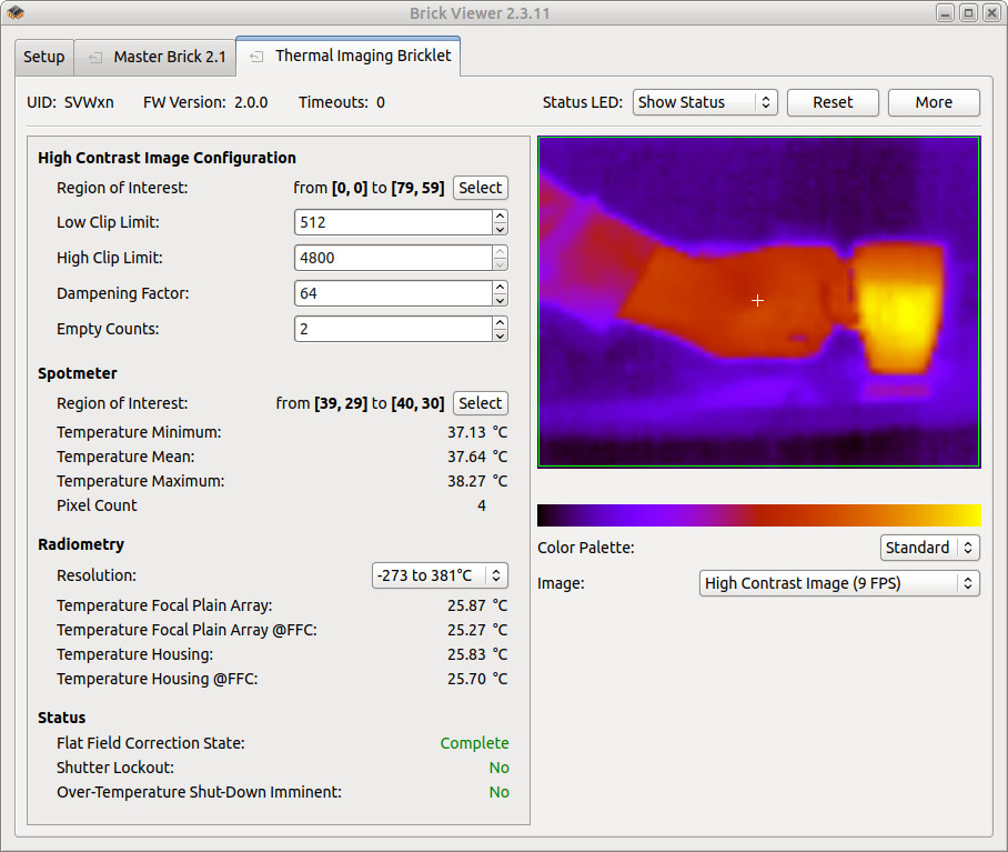
Test your Thermal Imaging Bricklet
To test a Thermal Imaging Bricklet you need to have Brick Daemon and Brick Viewer installed. Brick Daemon acts as a proxy between the USB interface of the Bricks and the API bindings. Brick Viewer connects to Brick Daemon. It helps to figure out basic information about the connected Bricks and Bricklets and allows to test them.
Connect the Thermal Imaging Bricklet to a Brick with a Bricklet Cable.
If you connect the Brick to the PC over USB, you should see a new tab named "Thermal Imaging Bricklet" in the Brick Viewer after a moment. Select this tab. If everything went as expected you can now see the thermal image and configure the Bricklet.
After this test you can go on with writing your own application. See the Programming Interface section for the API of the Thermal Imaging Bricklet and examples in different programming languages.
High Contrast Image vs Temperature Image
The Thermal Imaging Bricklet supports two type of image stream modes with different use cases.
High Contrast Image:
In High Contrast Image mode the Bricklet provides a 60x80 pixel image with a frame rate of 8.6Hz. Every pixel is a gray-scale representation and has a resolution of 8 bit.
This mode is used in FLIR based thermal imaging cameras that are available on the market. The data can be used for visualizations and it can be directly drawn to a display as is.
For the High Contrast Image mode the high dynamic range of the sensor is collapsed with a histogram-based non-linear mapping function. This filtering is necessary for visualizations. If the data would be unfiltered, it could not be used for visualizations. With a temperature range from -10°C and 450°C a common temperature image with small changes in the range of 20°C-30°C the changes would not be visible at all.
The 8 bit data of each pixel does not contain any temperature information anymore. However, even in High Contrast Image mode you can still use the spotmeter.
For the spotmeter you can define a region within the 60x80 pixel matrix. For this region you can then get the minimum, maximum and mean temperature for every frame. You can also define the spotmeter region to be only one pixel (to get the exact temperature of this pixel).
In this mode you can configure different parameters:
- Dampening Factor: This parameter is the amount of temporal dampening applied to the HEQ (history equalization) transformation function. An IIR filter of the form (N/256) * previous + ((256-N)/256) * current is applied, and the HEQ dampening factor represents the value N in the equation, i.e., a value that applies to the amount of influence the previous HEQ transformation function has on the current function. The lower the value of N the higher the influence of the current video frame whereas the higher the value of N the more influence the previous damped transfer function has.
- Clip Limit Low: This parameter defines an artificial population that is added to every non-empty histogram bin. In other words, if the Clip Limit Low is set to L, a bin with an actual population of X will have an effective population of L + X. Any empty bin that is nearby a populated bin will be given an artificial population of L. The effect of higher values is to provide a more linear transfer function; lower values provide a more non-linear (equalized) transfer function.
- Clip Limit High: This parameter defines the maximum number of pixels allowed to accumulate in any given histogram bin. Any additional pixels in a given bin are clipped. The effect of this parameter is to limit the influence of highly-populated bins on the resulting HEQ transformation function.
- Empty Counts: This parameter specifies the maximum number of pixels in a bin that will be interpreted as an empty bin. Histogram bins with this number of pixels or less will be processed as an empty bin.
Additionally a region of interest can be defined. The algorithms configured by the above parameters will only be applied for the specified region. This region can be defined to exclude parts of the image that are not to be analyzed and would otherwise distort the data. As an example it might be interesting to exclude a hot spot in the image.
Use this mode if you need any form of visualization of the data.
Temperature Image:
In Temperature Image mode the Bricklet provides a 60x80 pixel image with a frame rate of 4.5Hz. Every pixel in this image is a temperature measurement with a resolution of 16 bit.
The Thermal Imaging Bricklet has two configurable temperature ranges for the Temperature Image mode:
- -10°C to 140°C with a resolution of 0.01°C
- -10°C to 450°C with a resolution of 0.1°C
If you don't need to measure temperatures above 381°C you should always use the first range to increase the resolution.
The data can be directly used for scientific calculations or to analyze absolute temperature changes.
Use this mode if you want to work with actual temperature data.
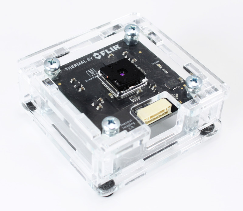
Thermal by FLIR
The Tinkerforge Thermal Imaging Bricklet is equipped with a Lepton thermal imaging sensor. Tinkerforge is part of the Thermal by FLIR program (please note the logo on the front side of the Bricklet). Thermal by FLIR is a program where FLIR is working with leading integrators to support development and marketing of products that include FLIR thermal sensors. The goal of the program is aligned with FLIR's mission of innovating the sixth sense to saves lives and livelihoods.
FLIR has created a central site at lepton.flir.com to support the Lepton maker community.
Case
A laser-cut case for the Thermal Imaging Bricklet is available.
The assembly is easiest if you follow the following steps:
- screw 12mm screw with nut to the top plate
- Build up side plates,
- plug side plates into top plate,
- screw 10mm spacers to the Bricklet and
- screw bottom plate to spacers.
Below you can see an exploded assembly drawing of the Thermal Imaging Bricklet case:
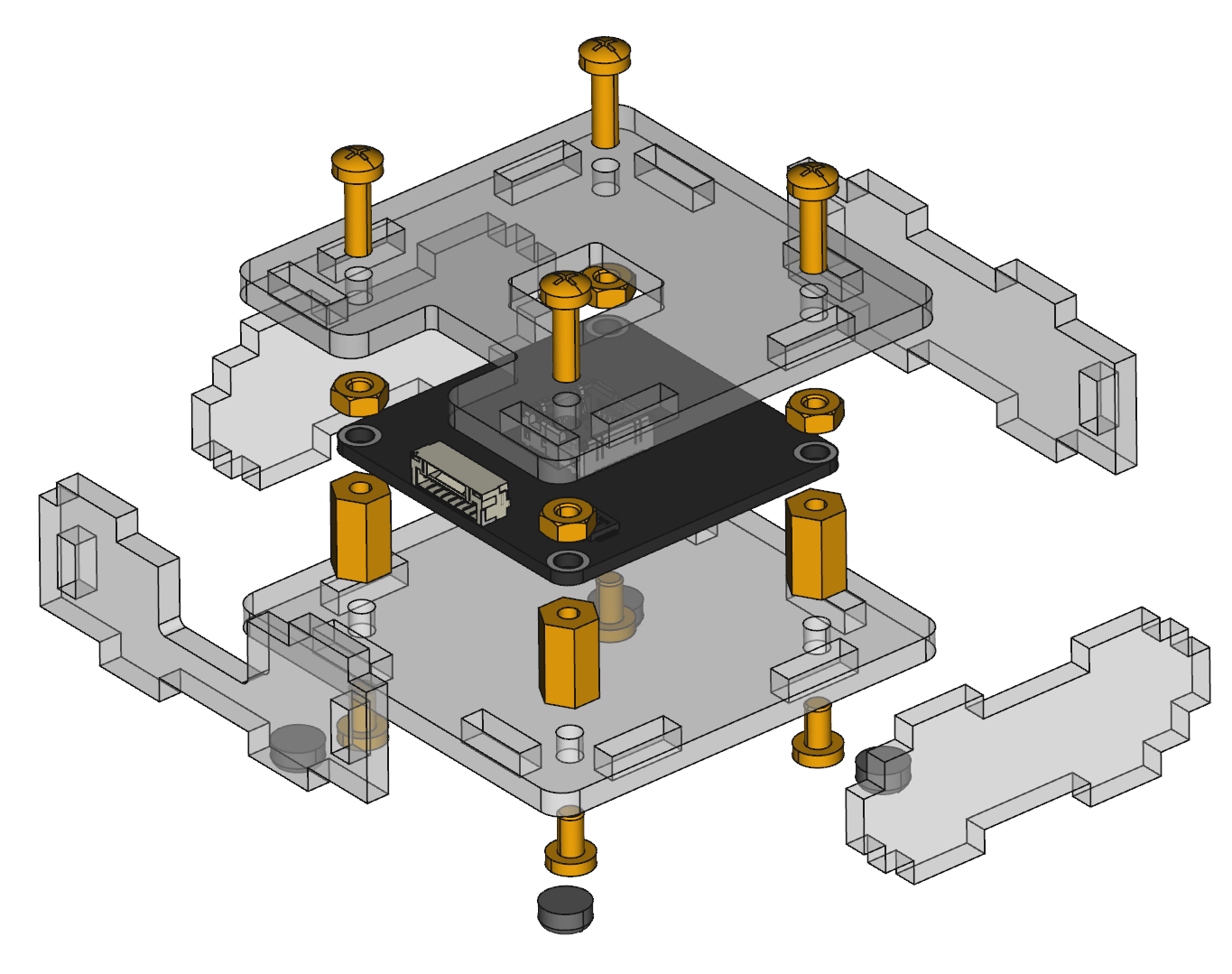
Hint: There is a protective film on both sides of the plates, you have to remove it before assembly.
Programming Interface
See Programming Interface for a detailed description.
| Language | API | Examples | Installation |
|---|---|---|---|
| C/C++ | API | Examples | Installation |
| C/C++ for Microcontrollers | API | Examples | Installation |
| C# | API | Examples | Installation |
| Delphi/Lazarus | API | Examples | Installation |
| Go | API | Examples | Installation |
| Java | API | Examples | Installation |
| JavaScript | API | Examples | Installation |
| LabVIEW | API | Installation | |
| Mathematica | API | Examples | Installation |
| MATLAB/Octave | API | Examples | Installation |
| MQTT | API | Examples | Installation |
| openHAB | API | Examples | Installation |
| Perl | API | Examples | Installation |
| PHP | API | Examples | Installation |
| Python | API | Examples | Installation |
| Ruby | API | Examples | Installation |
| Rust | API | Examples | Installation |
| Shell | API | Examples | Installation |
| Visual Basic .NET | API | Examples | Installation |
| TCP/IP | API | ||
| Modbus | API |