- Getting Started
- Hardware
- Software
- Kits
- Starter Kit: Weather Station
- Starter Kit: Hardware Hacking
- Starter Kit: Server Room Monitoring
- Starter Kit: Server Room Monitoring 2.0
- Starter Kit: Blinkenlights
- Starter Kit: Internet of Things
- Starter Kit: Camera Slider
- Tabletop Weather Station
- Embedded Boards
- Specifications
Smoke Detector Hardware Setup
Typically a smoke Detector is equipped with one or more LEDs that signal the state. The number and behavior of the LEDs will depend on the used model.
In this example we use a wirelessly interconnectable smoke detector. That means, you can put a smoke detector in different rooms and if smoke is detected, all of the smoke detectors will start making noise.
This is perfect for our hacking purposes. We can hack one of the smoke detectors and place it next to the PC. It will be triggered by the other smoke detectors that are scattered throughout the house and we can read out its state.
The innards of the Smoke Detector
The ELRO FA20RF/2 has two LEDs next to the "TEST" and "LEARN" buttons.

If we start a test alarm, we can see that the LED on the right side blinks green every time an alarm is triggered.
Now that we have located an LED that represents the state we want to read out, we can open the casing of the detector. In our case it looks like the following:
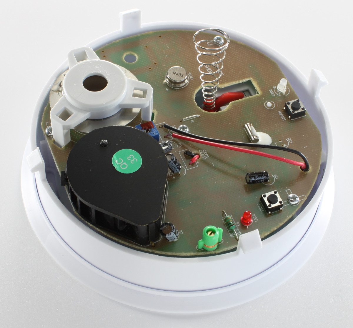
The LED in question is the transparent LED on the top right. It is a two-color LED and it can blink green as well as red. We will have to find the pins that control the green color of the LED.
Since the LED is of through-hole type (not SMD), the contacts are only exposed at the bottom.
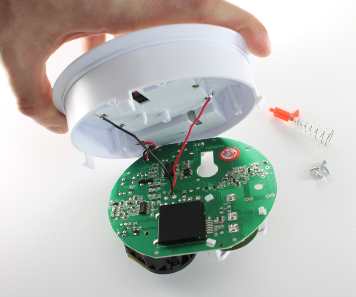
We have to remove the screws to get to the other side of the circuit board.
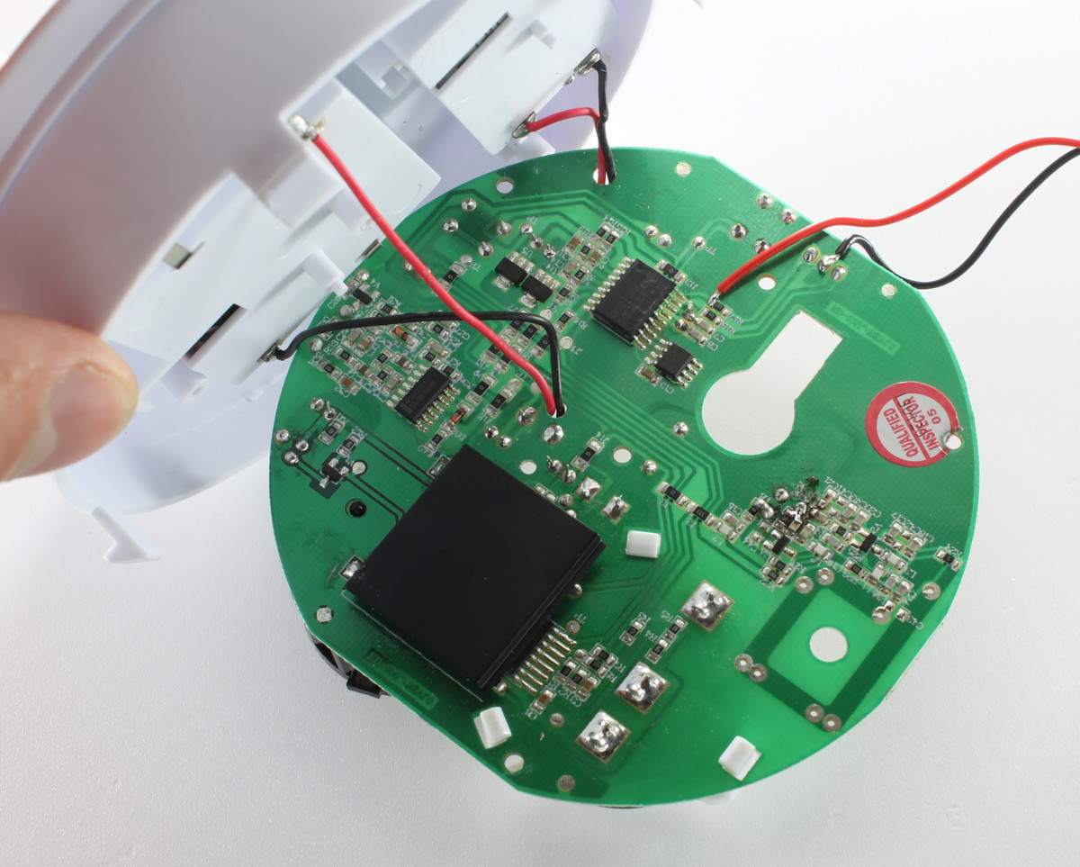
The three solder pads at the top, left to the red sticker belong to the LED. We will have to solder wires to them.
Soldering Wires to the LED and its Series Resistor
See here for a basic soldering tutorial and here for instructions how you can find the correct pins of the LED and its series resistor.
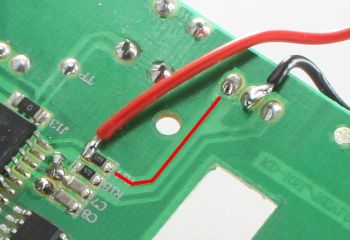
In case of the ELRO FA20RF/2 the transparent LED consists in fact of two LEDs (one green and one red) in one casing. Both LEDs have one common pin (center) and one individual pin (pin left, right). To light the green LED the left pin is used.
We solder one wire to the center pin of the LED and trace the circuit from the left pin until we find the resistor (marked in red). The cable is soldered behind this resistor.
After that we can screw the circuit board back to the casing. We connect the wires to the + and - of port 0 of the Industrial Digital In 4 Bricklet. We can check if the polarity is correct later with the Brick Viewer.
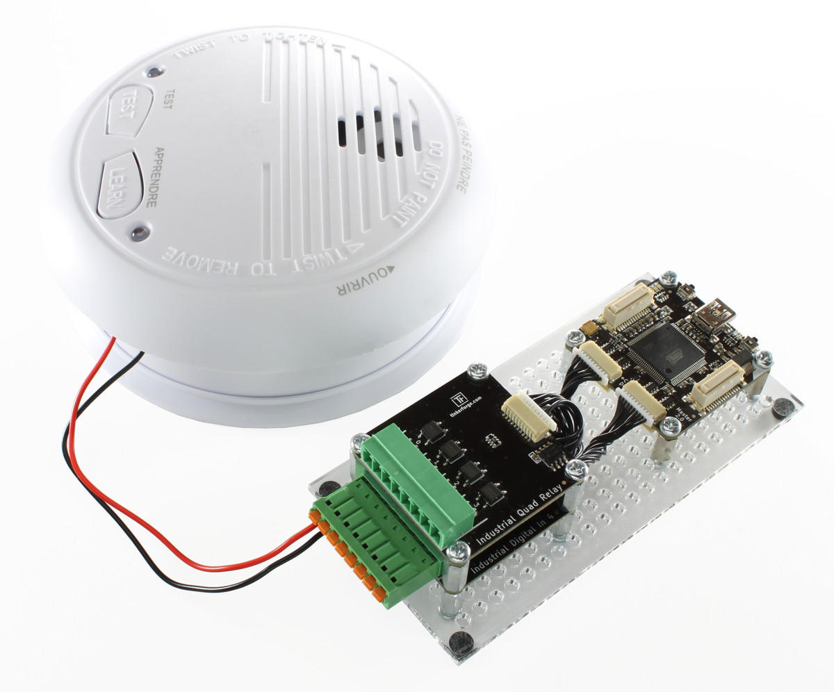
Now we can test the hacked smoke detector. To do that, we press the test button. The reaction of the LED should be represented in the Brick Viewer.
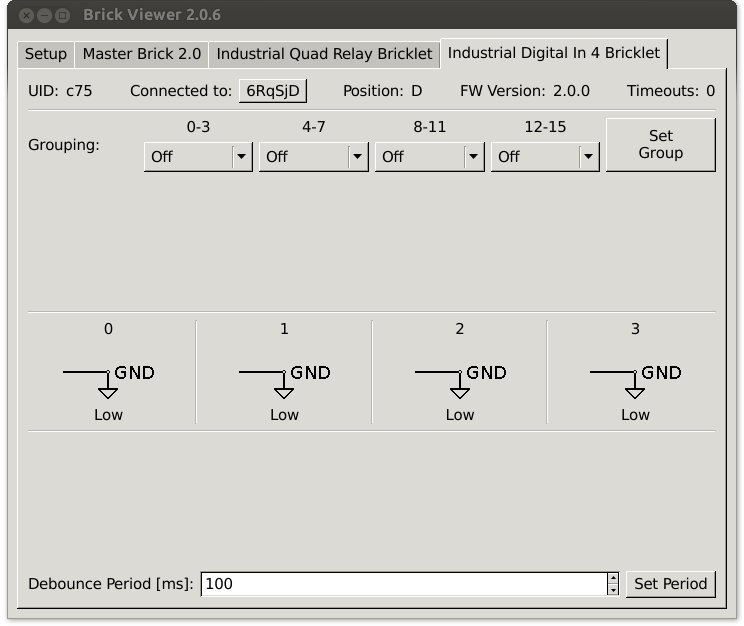
If the state of the input does not change in Brick Viewer the wires are most likely reversed. In this case you have to swap them.