- Getting Started
- Hardware
- Software
- Kits
- Starter Kit: Weather Station
- Starter Kit: Hardware Hacking
- Starter Kit: Server Room Monitoring
- Starter Kit: Server Room Monitoring 2.0
- Starter Kit: Blinkenlights
- Starter Kit: Internet of Things
- Starter Kit: Camera Slider
- Tabletop Weather Station
- Embedded Boards
- Specifications
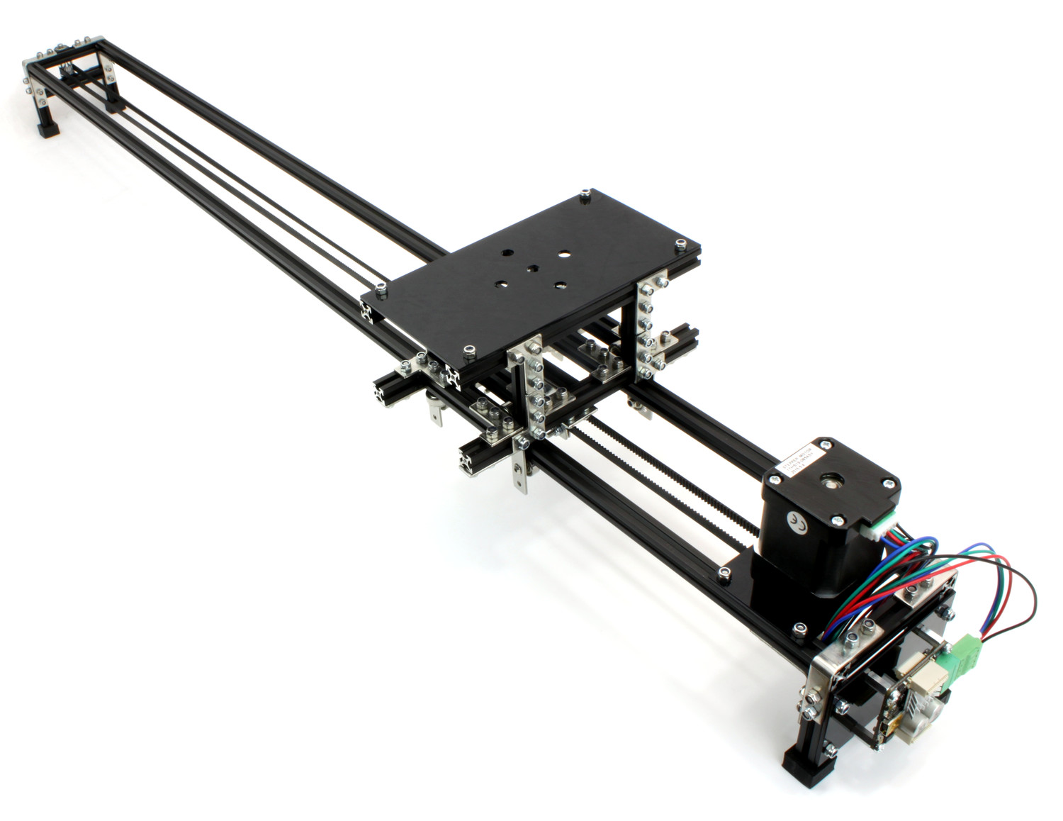
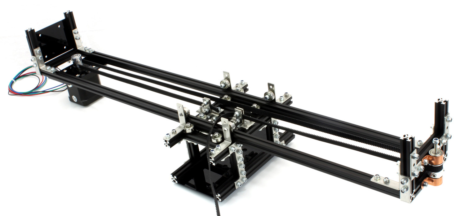
Construction - Basic Camera Slider
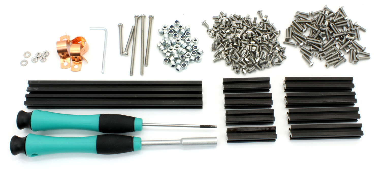
The basic kit contains the following parts:
1x Bearing Set
1x Hinge Set
1x Stepper Brick (including Mini USB Cable 180cm and Mounting Kit 12mm)
The Camera Slider consists of two main parts, the frame and the cart. The constructions starts with the legs of the frame.
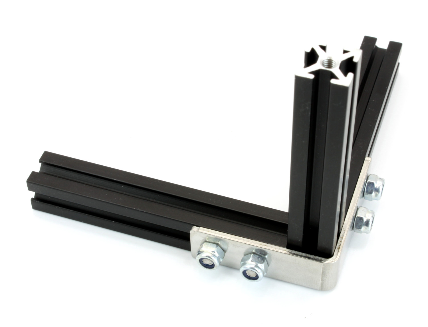
Legs
Each pair of legs consists of three 60mm MakerBeams connected by two MakerBeam Corner Brackets to form an upside down U-shape:
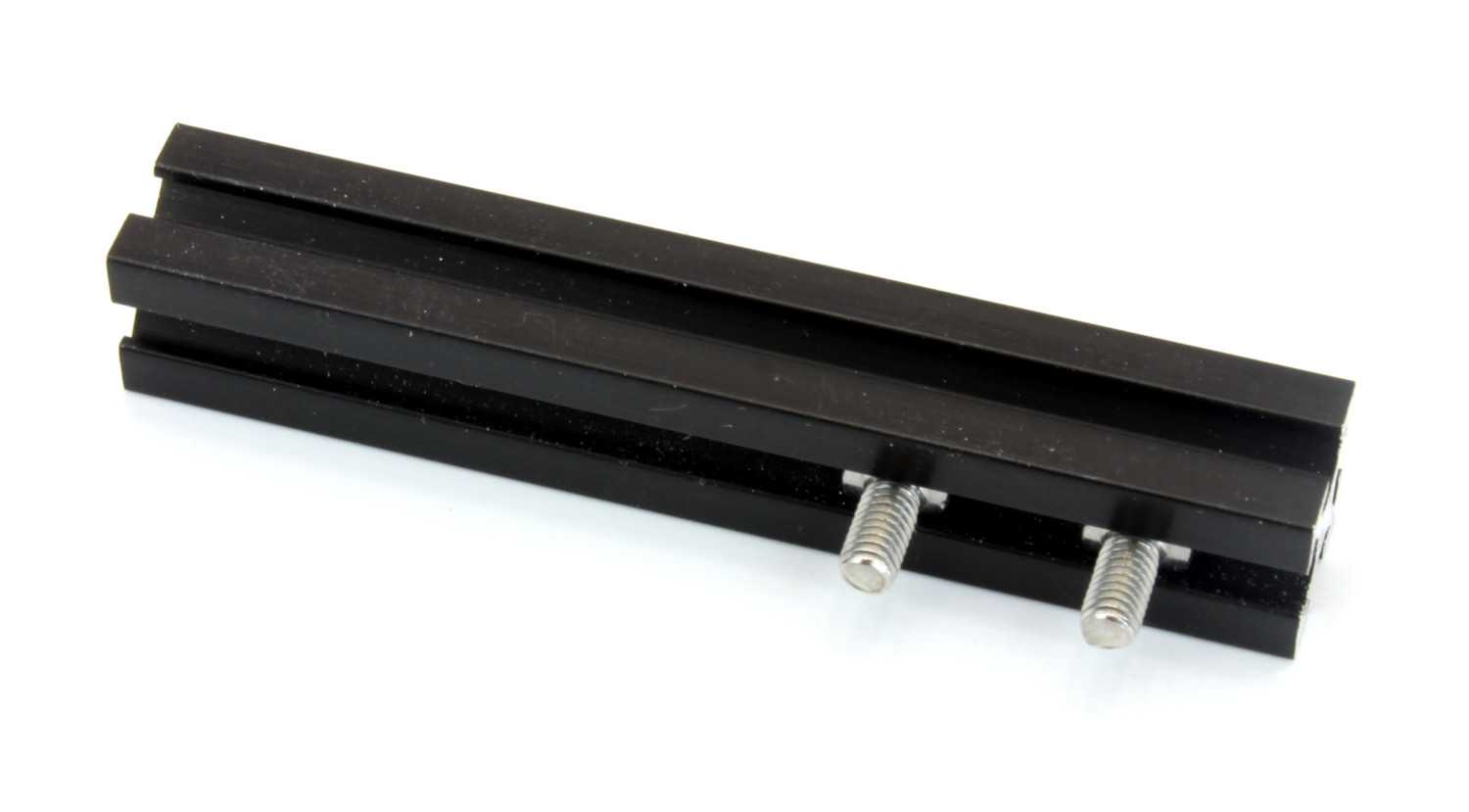
Insert two 6mm bolts into a 60mm MakerBeam.
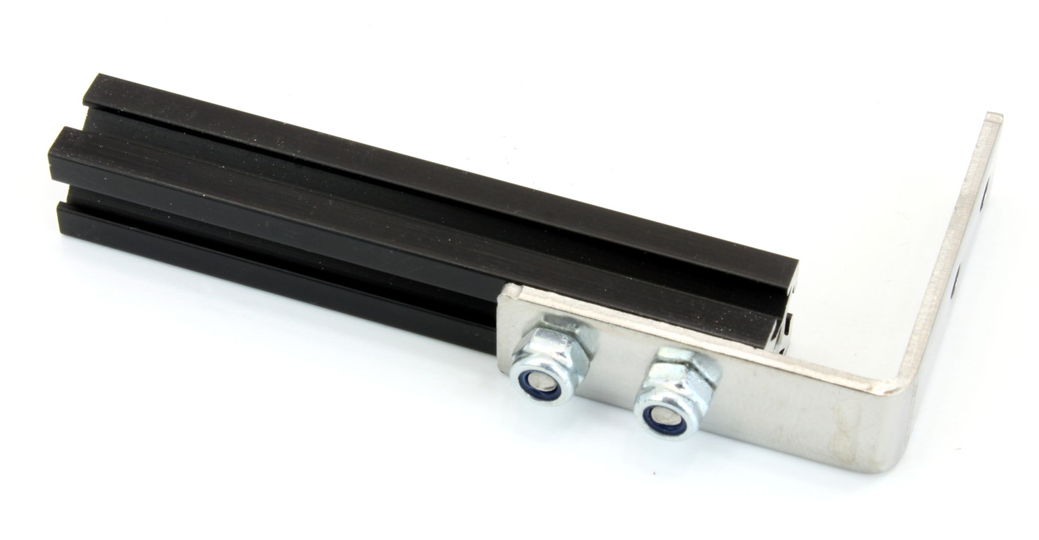
Fasten a MakerBeam Corner Bracket to the MakerBeam with two lock nuts. Use another MakerBeam as temporary spacer in the corner of the bracket.
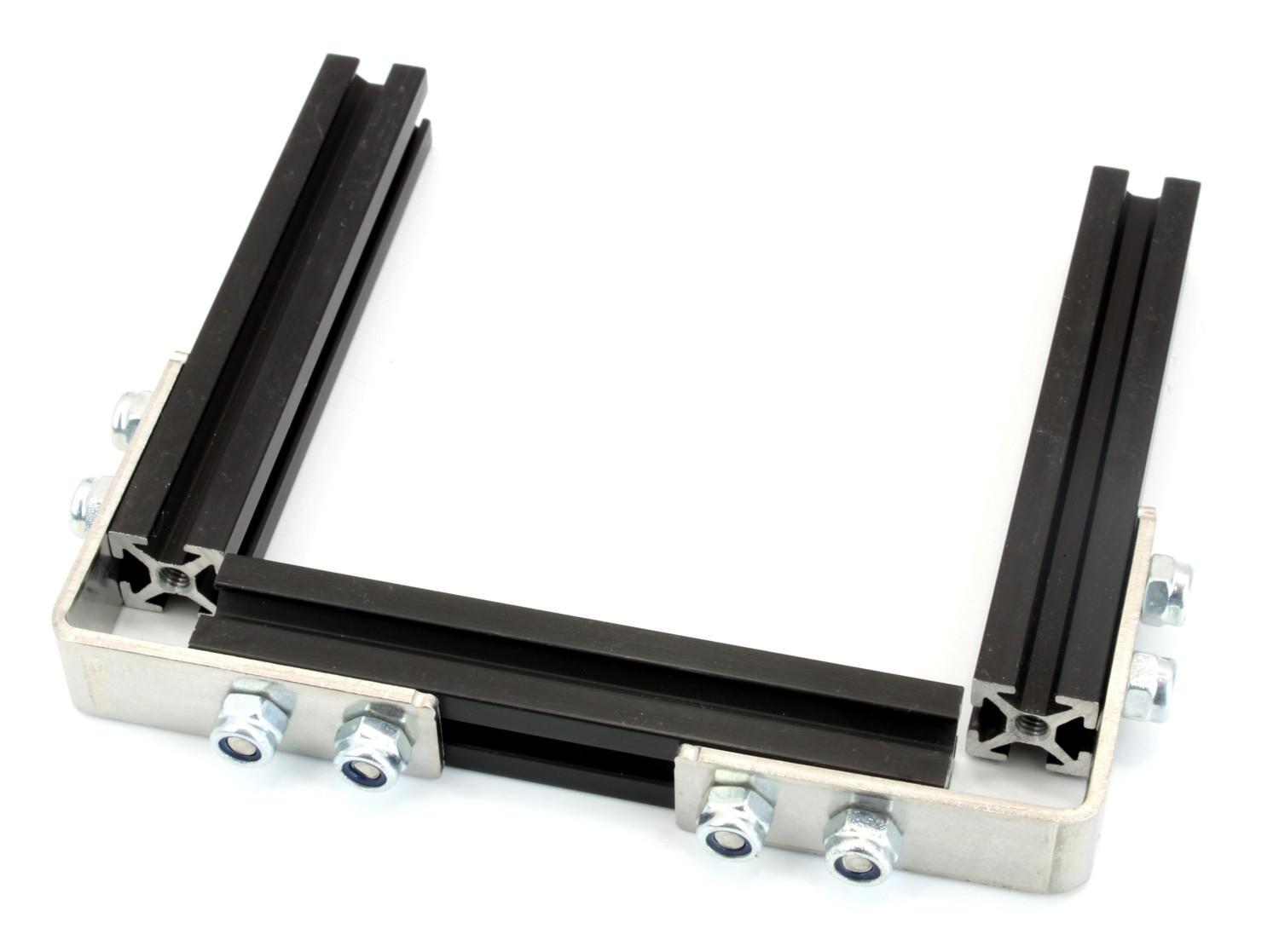
Repeat these steps three times to create a U-shaped pair of legs. Then repeat all steps for the second pair of legs.
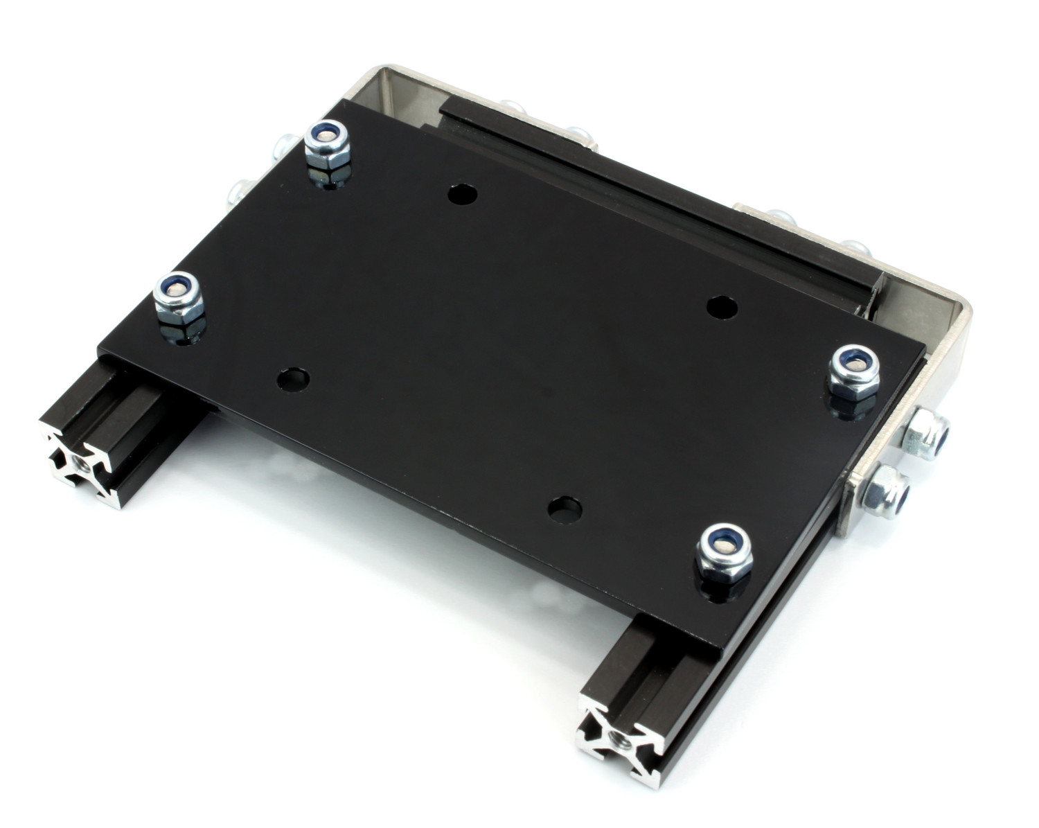
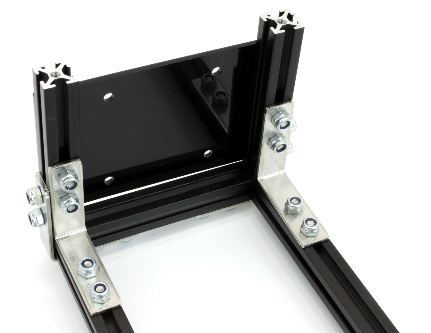
Stack Side
One pair of legs gets the stack bracket attached to it:
Insert two 6mm bolts into the upright MakerBeams of each leg.
Fasten the stack bracket to the upright MakerBeams with four lock nuts. Ensure that the bracket does not overlap the crossbeam.
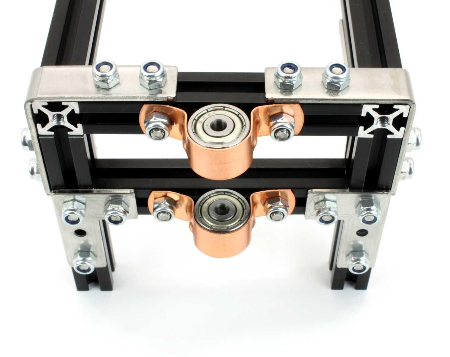
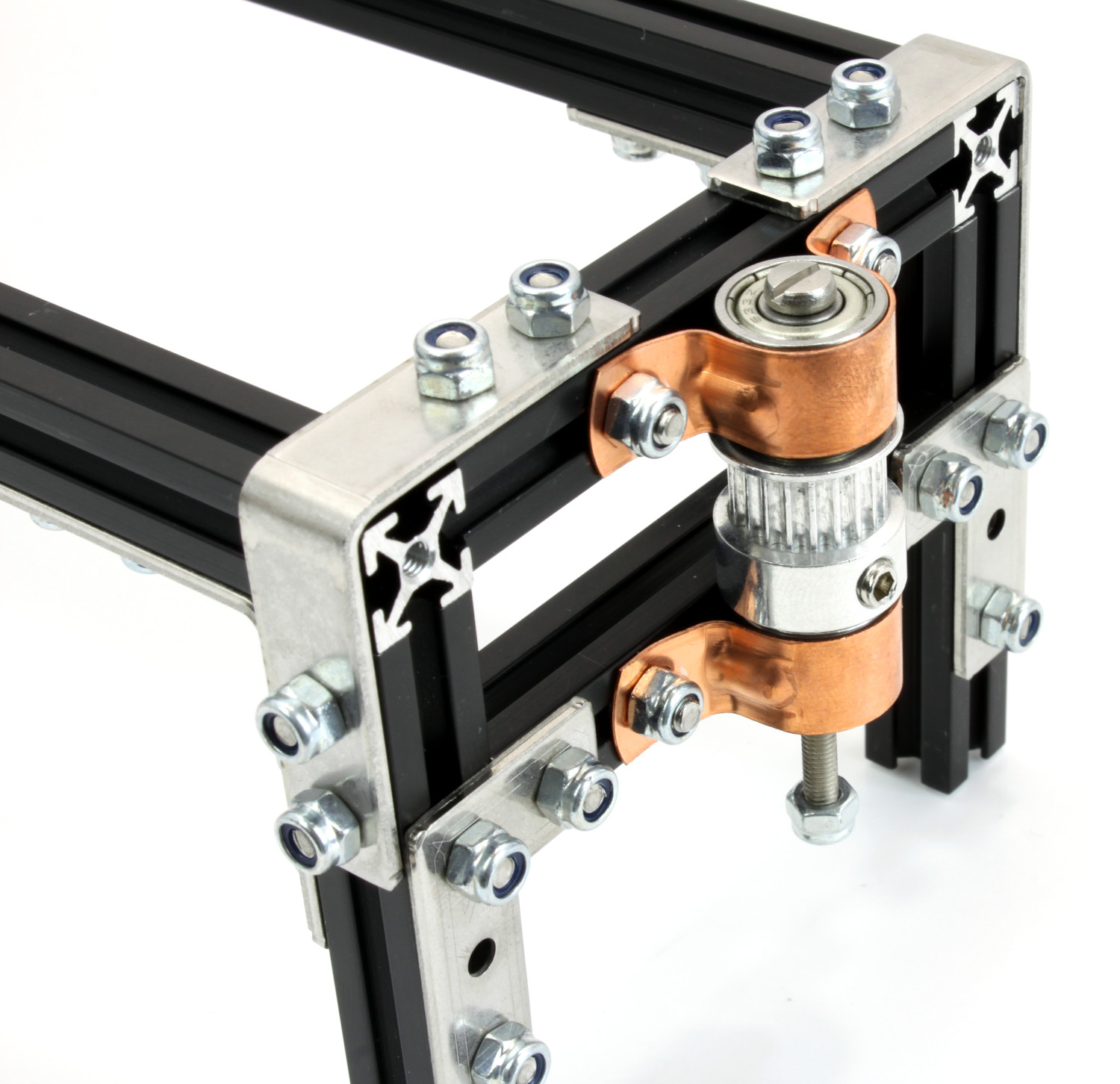
Idler Pulley Side
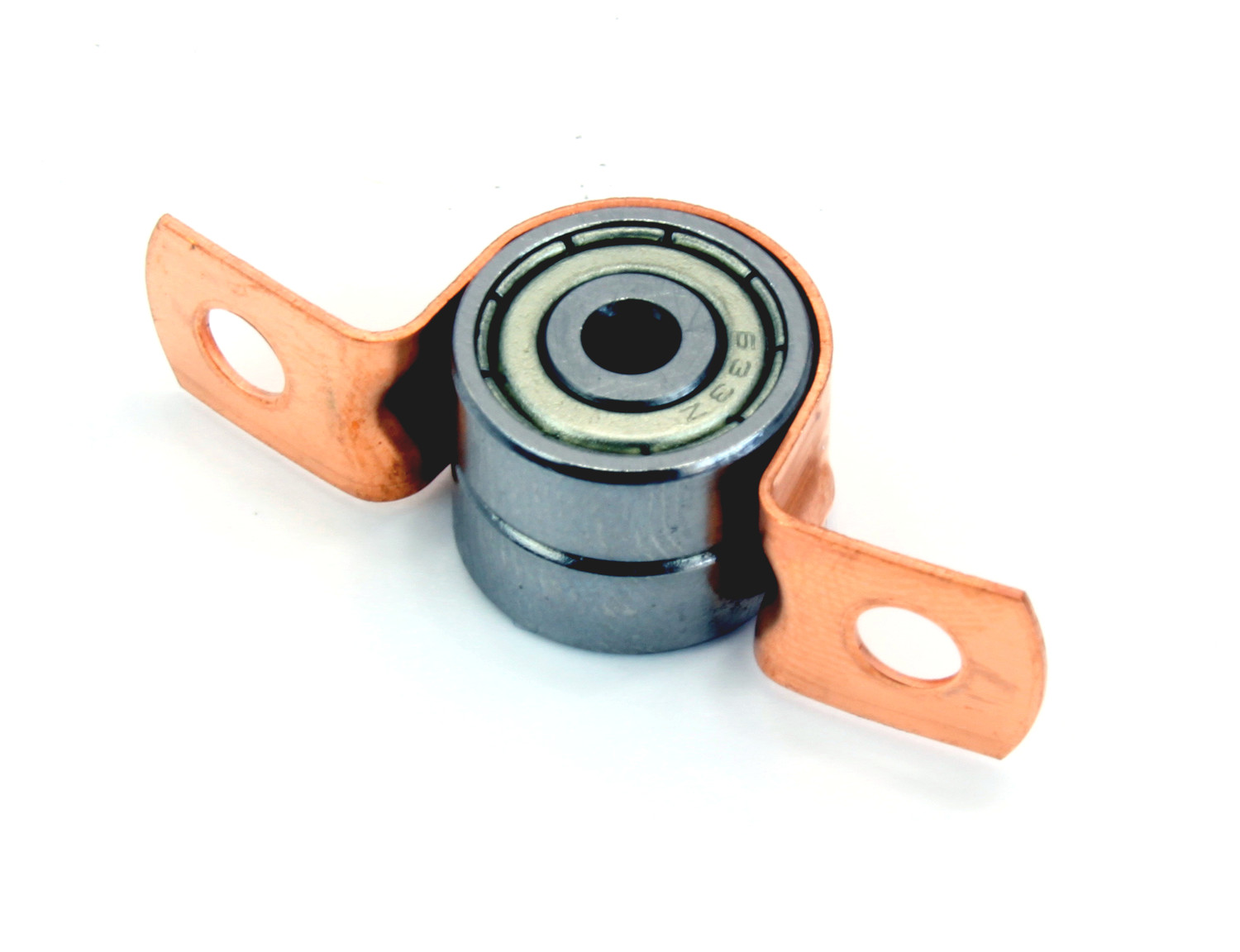
The other pair of legs gets bearings attached to it for the idler pulley. Start with the bearings on the crossbeam:
Place two bearings into a copper saddle band clip.
Insert two 6mm bolts into the crossbeam.
Fasten the bearing assembly to the middle of crossbeam with two lock nuts.
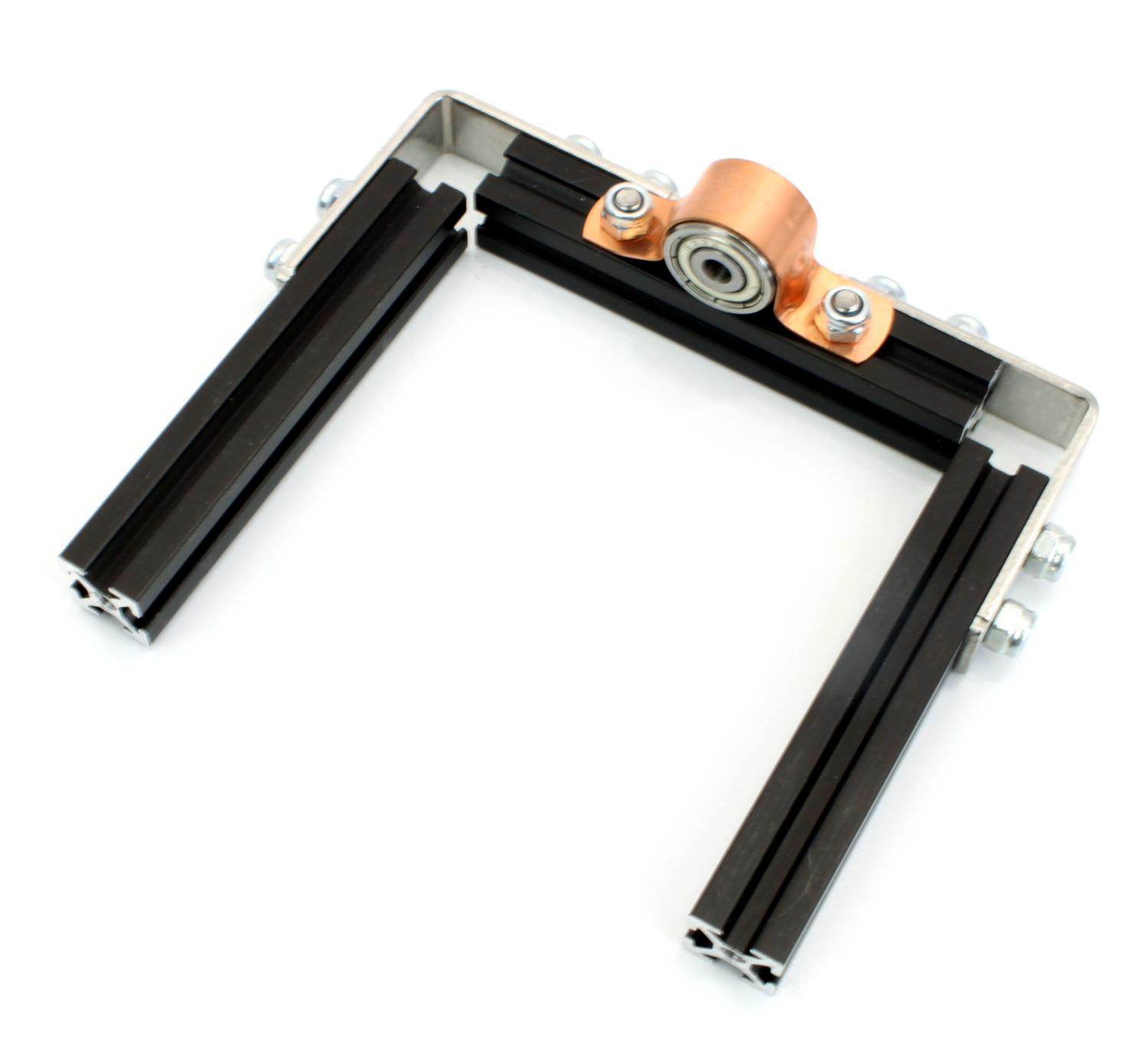
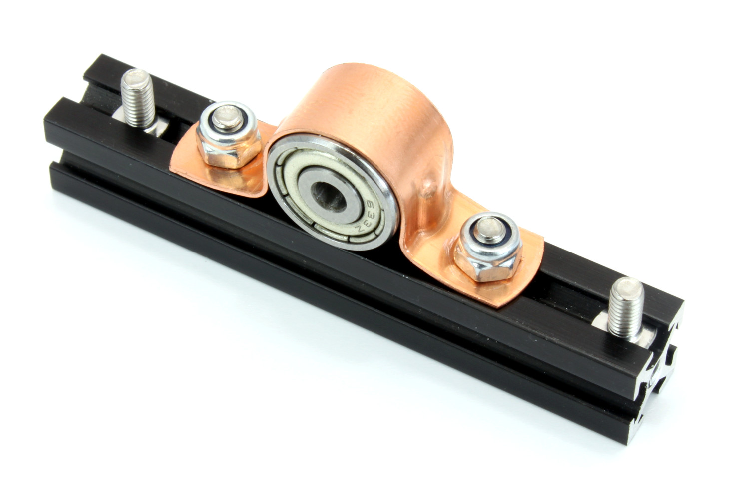
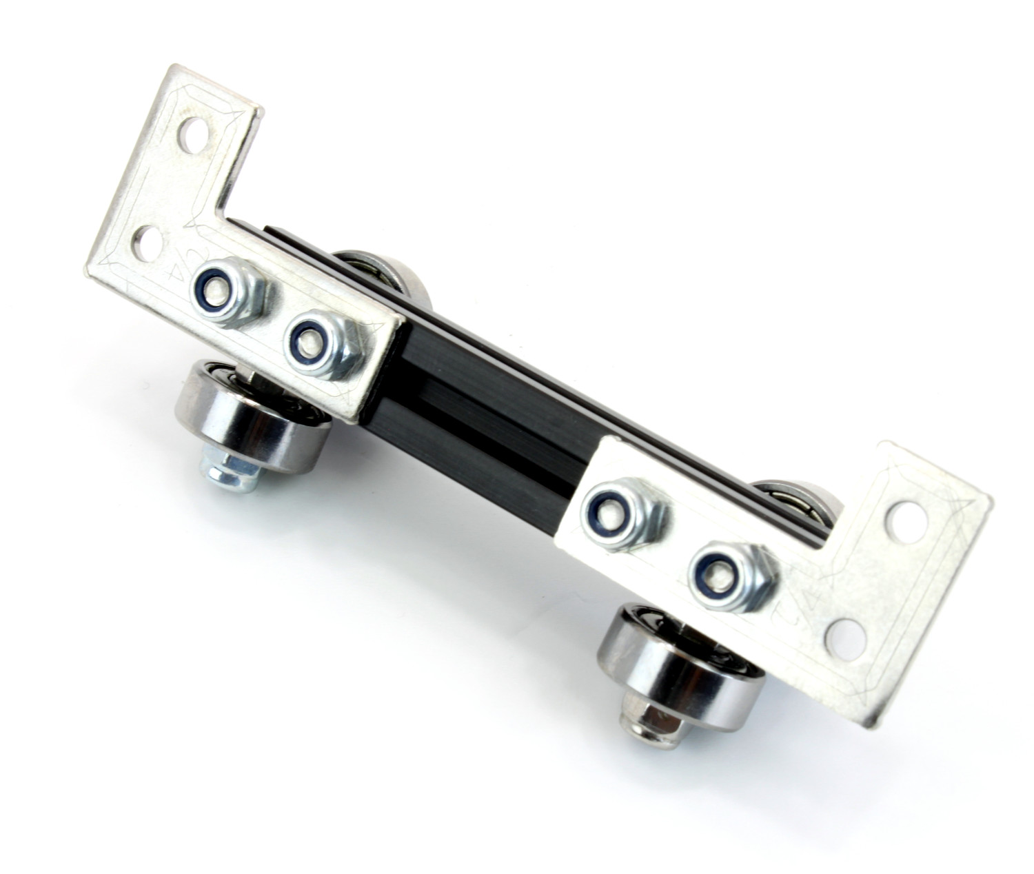
A second bearing assembly gets attached to a 60mm MakerBeam:
Place two bearings into a copper saddle band clip.
Insert two 6mm bolts into a 60mm MakerBeam.
Fasten the bearing assembly to the middle of the MakerBeam with two lock nuts.
Insert a 6mm bolt into the MakerBeam on each side of the bearing assembly.
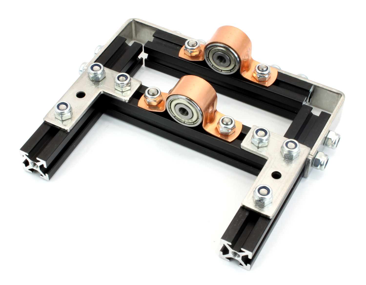
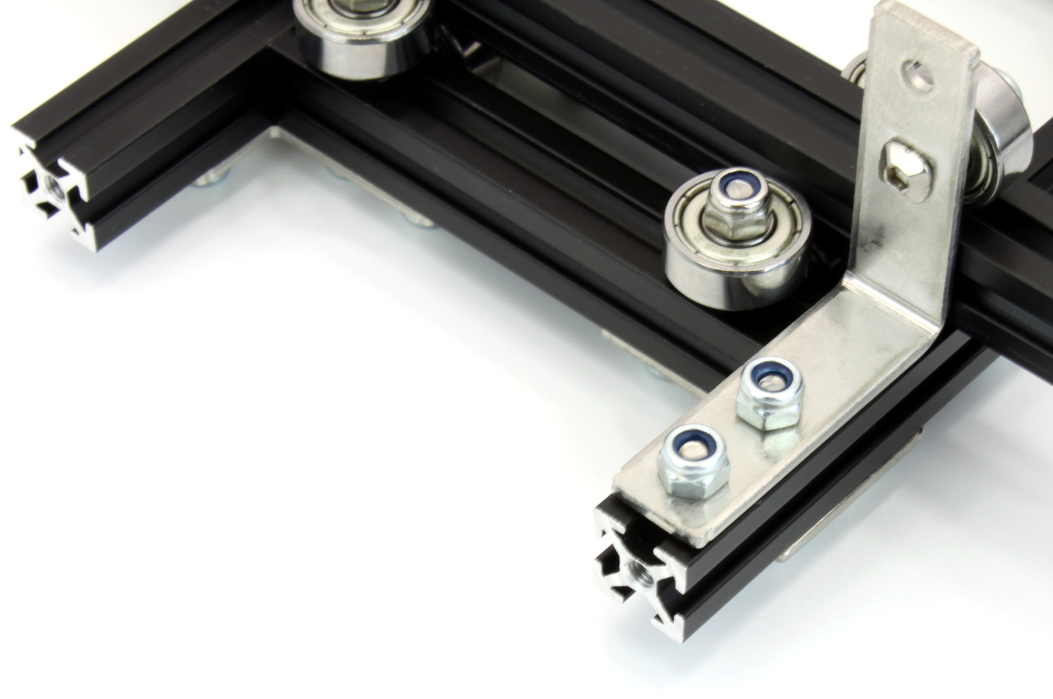
The MakerBeam-bearing assembly gets attached to the legs:
Insert two 6mm bolts into each upright MakerBeam of the pair of legs.
Fasten the MakerBeam-bearing assembly to the upright MakerBeams with one MakerBeam L-Bracket and four lock nuts each.
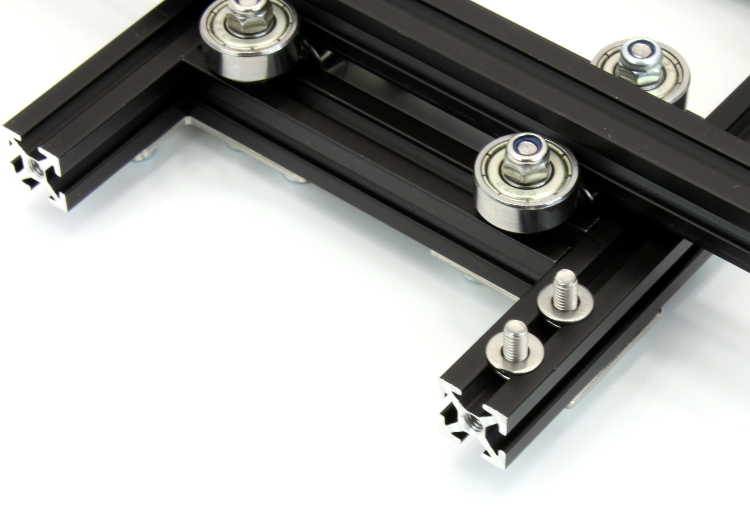
Frame
The legs and two 900mm MakerBeams form the frame.
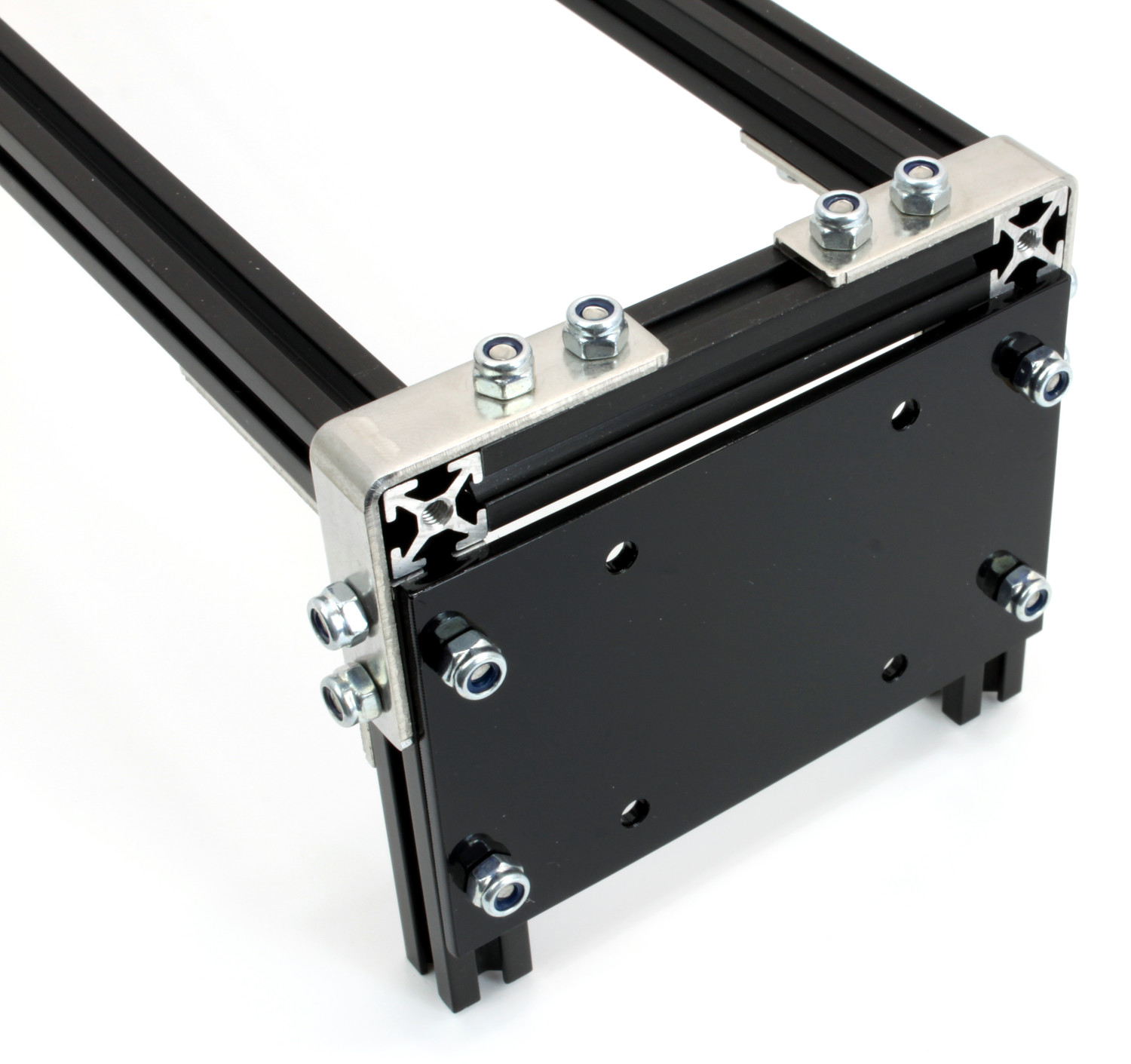
Stack Side
Start with the stack-side legs:
Insert two 6mm bolts into the upright MakerBeam of each stack-side leg opposite to the stack bracket.
Fasten two MakerBeam Corner Brackets to the upright MakerBeams with two lock nuts each. Ensure that the brackets are flush with the top edge of the MakerBeams.
Insert two 6mm bolts into each 900mm MakerBeam.
Fit the MakerBeams into the corners of the pair of stack-side legs and fasten them with two lock nuts each.
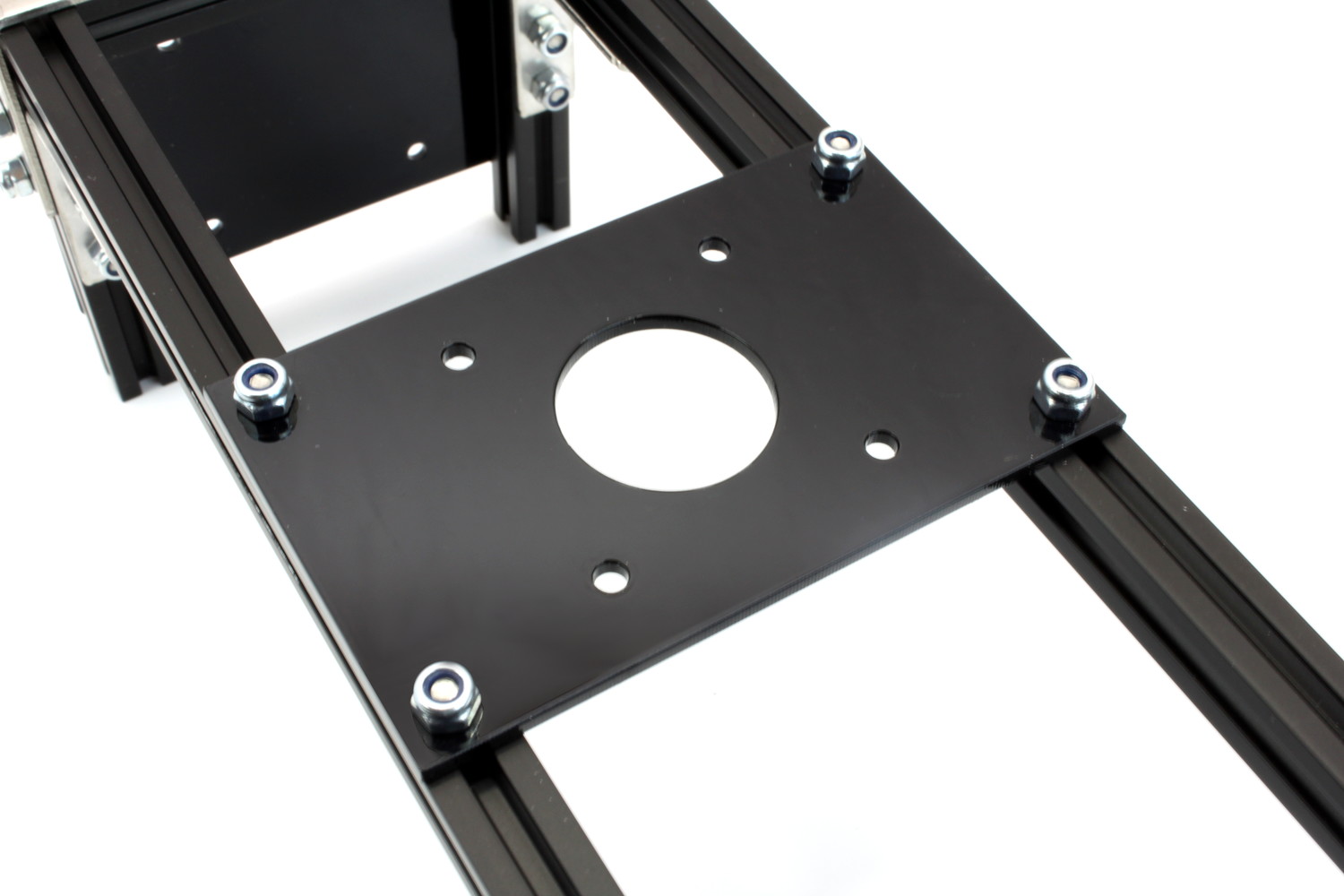
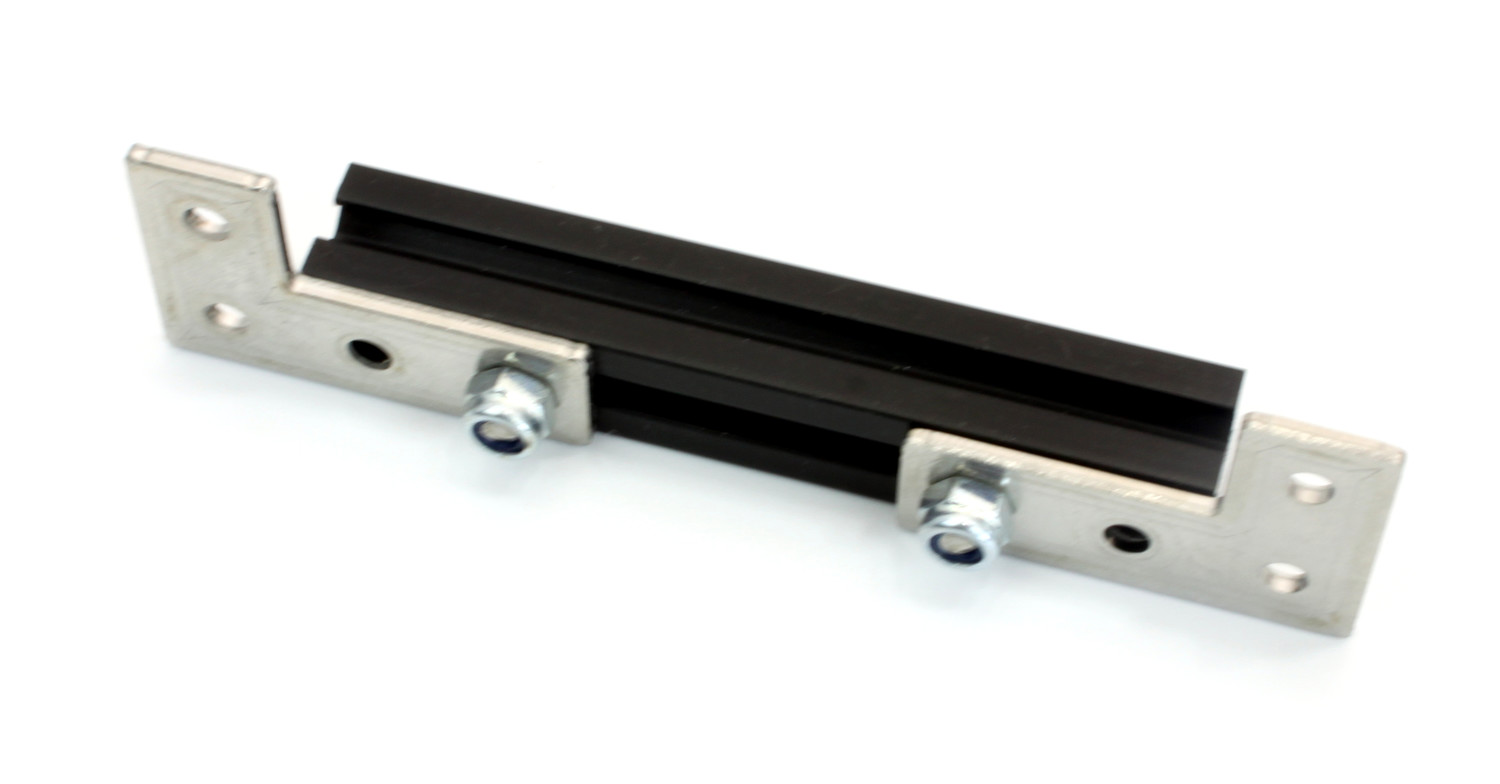
Next the stepper motor bracket gets attached to the frame:
Insert two 6mm bolts into the top side of each 900mm MakerBeam.
Fasten the stepper motor bracket to the MakerBeams with four lock nuts.
Idler Pulley Side
To complete the frame attach the idler-pulley-side legs to the other end of the 900mm MakerBeams, the same way the stack-side legs got attached.
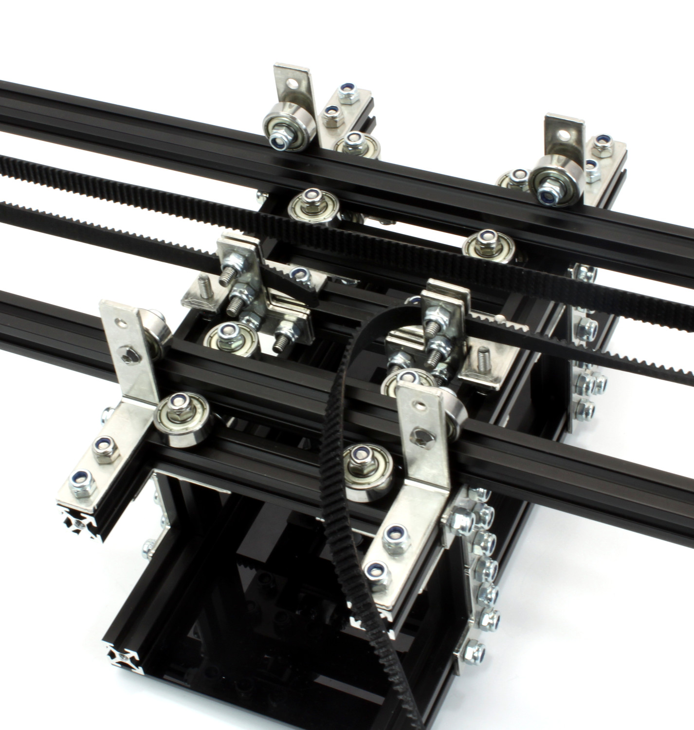
Cart
The cart rolls on top of the frame.
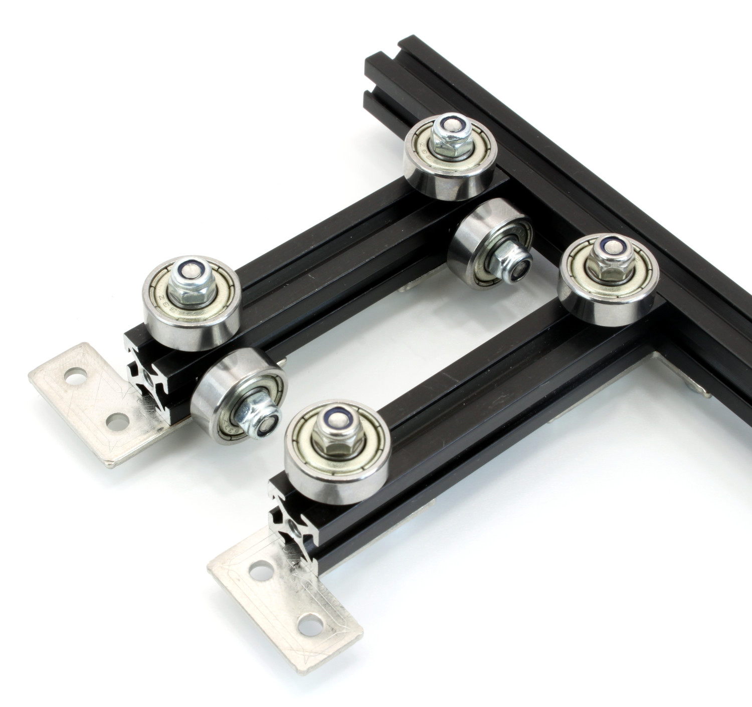
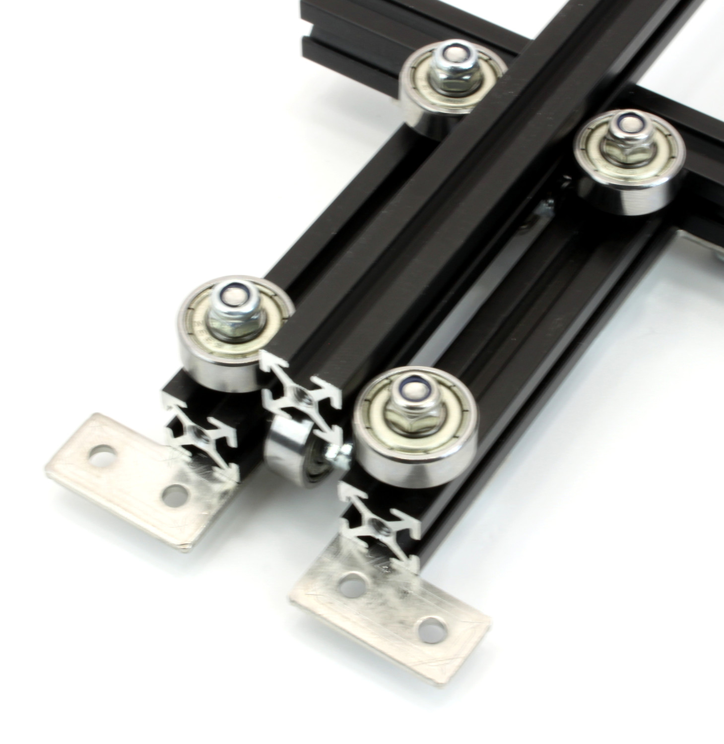
Bearing Assemblies
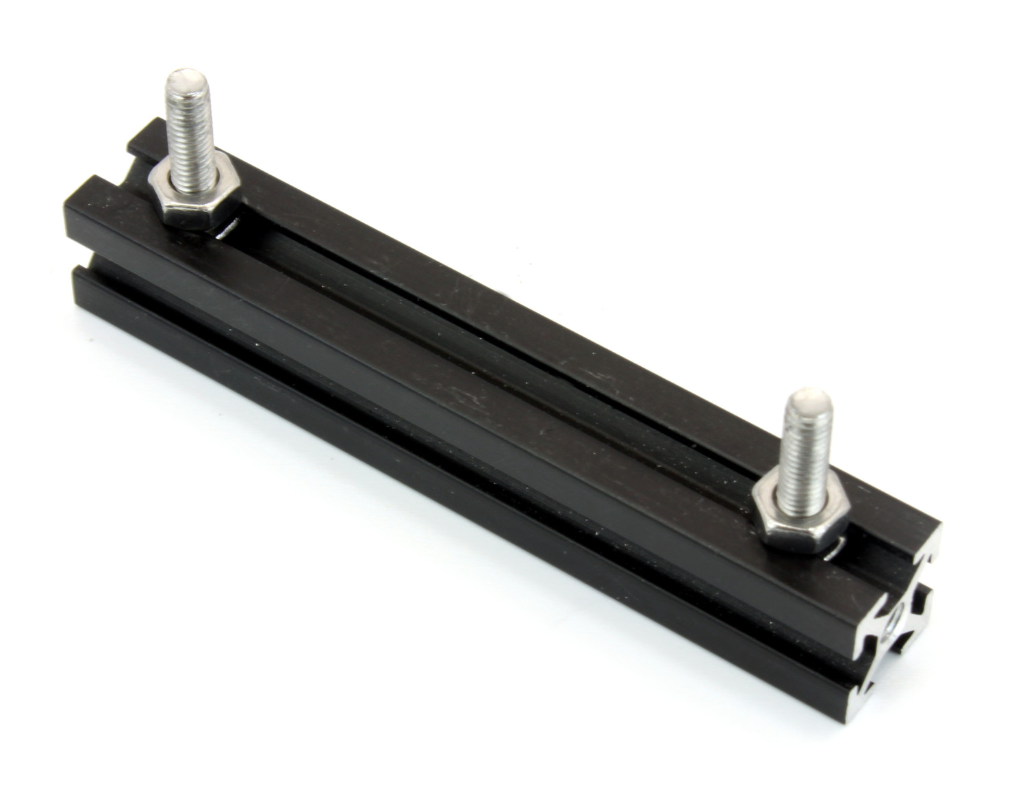
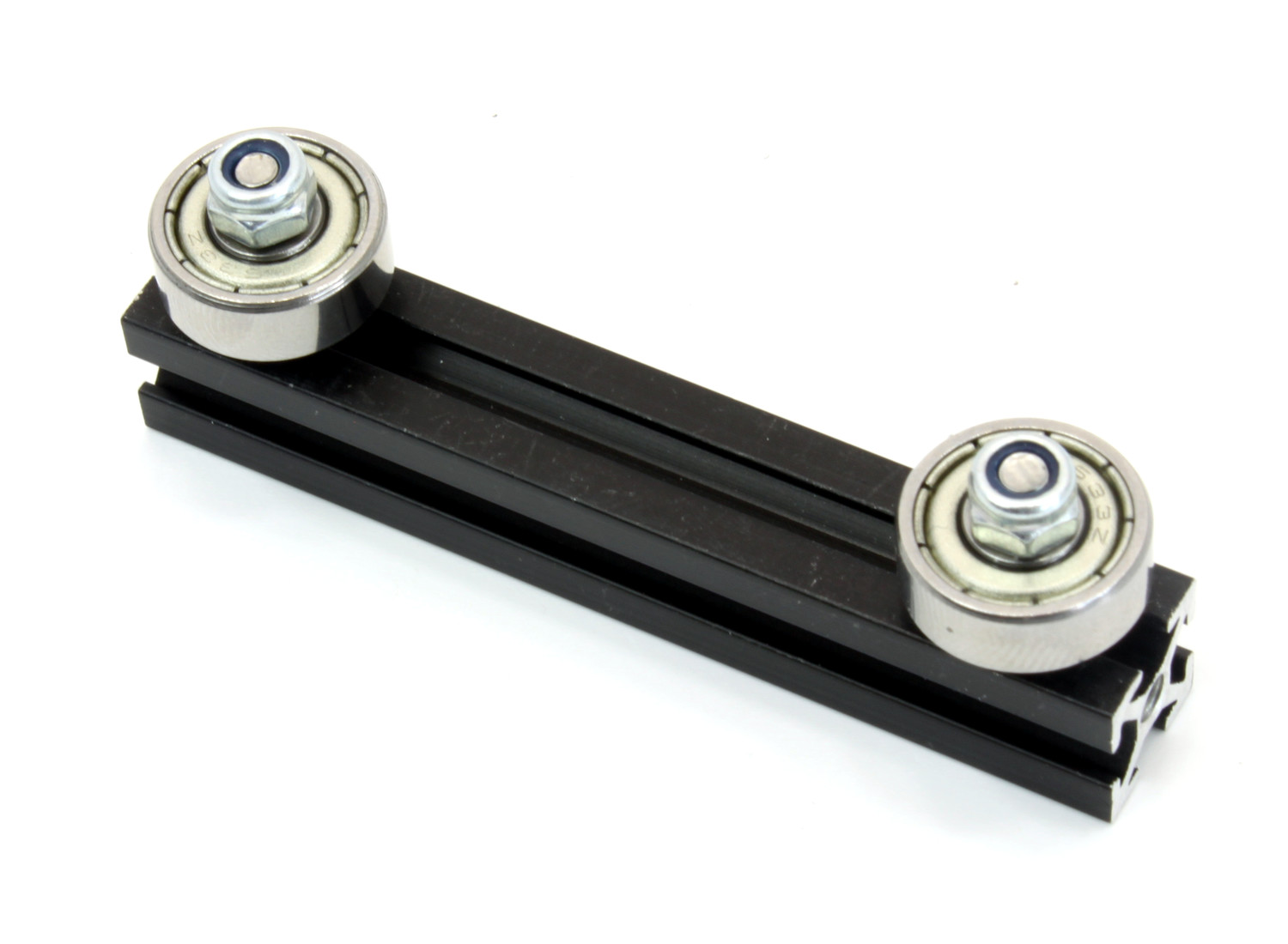
The construction starts with attaching twelve bearings to four 60mm MakerBeams. These bearings will roll on top and on the sides of the frame:
Insert two 12mm bolts into a 60mm MakerBeam and fasten each one with a normal nut, not a lock nut. The bolts should be located about 7mm from the ends of the MakerBeam.
Put a bearing onto each bolt and fasten it with a lock nut each. Ensure that the bearing is near to the edge of the MakerBeam but does not protrude beyond it.
Repeat these steps three times to create four MakerBeams with two bearings each.
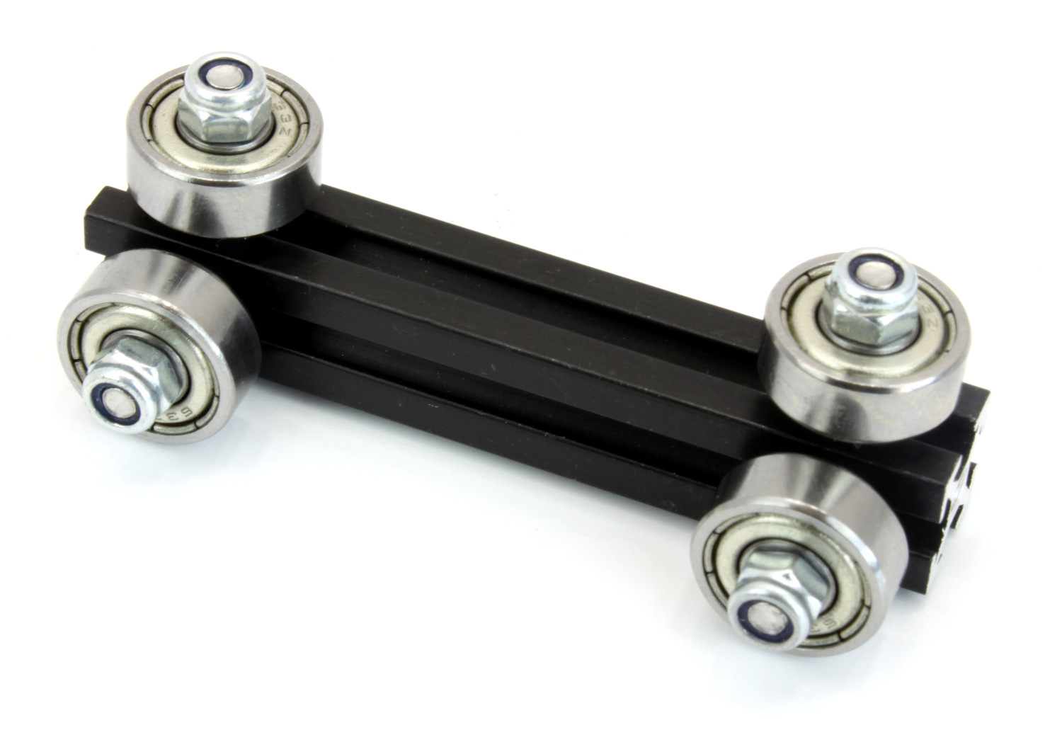
Two of the four MakerBeams get two additional bearings each. Attach the bearings at an 90° angle to the already attached ones, the same way the first two bearings got attached.
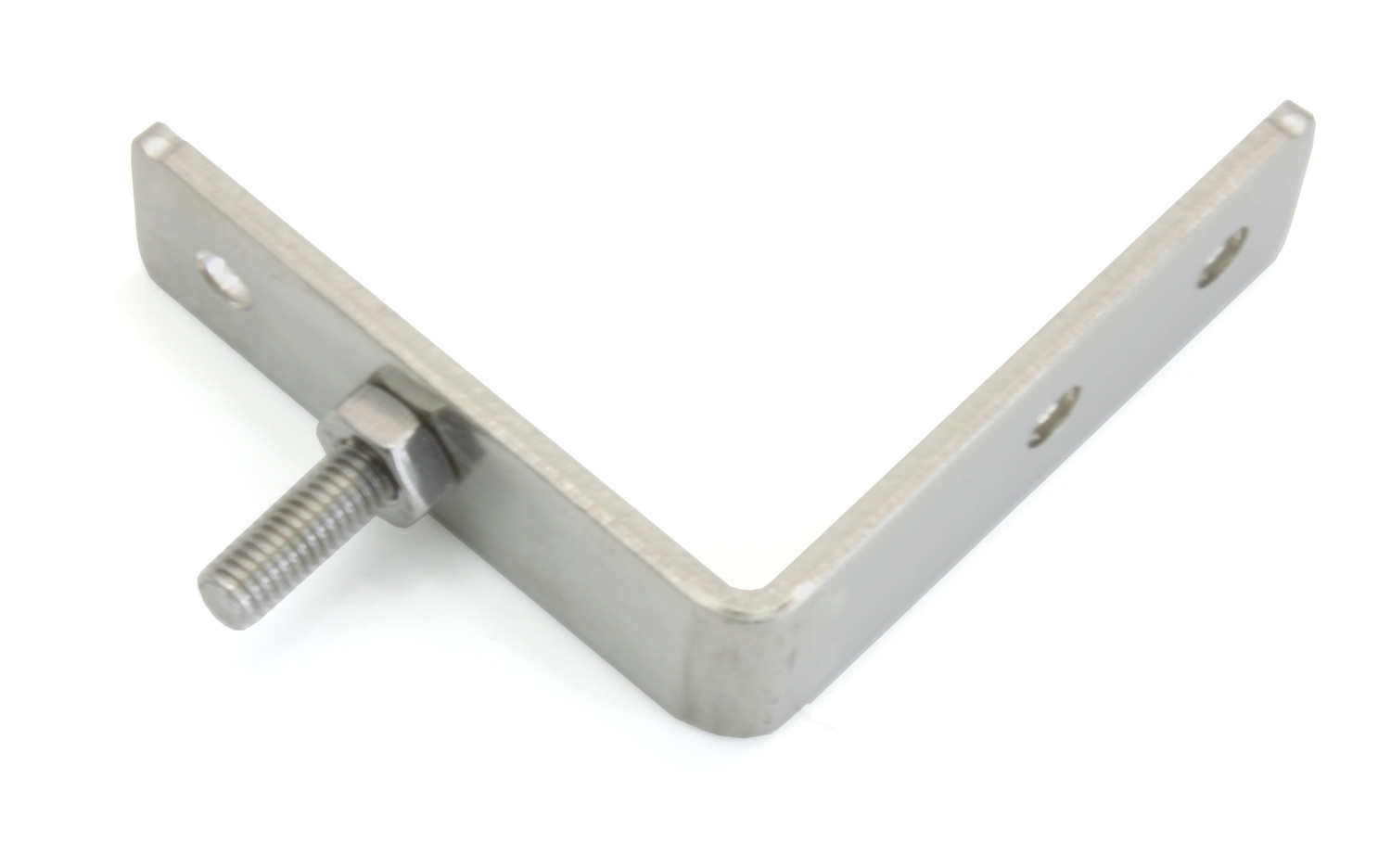
Add L-brackets to the 2-bearing assemblies:
Insert four 6mm bolts into the MakerBeam opposite to the bearings.
Fasten two MakerBeam L-Brackets to the MakerBeam with two lock nuts each.
Repeat these steps for the second 2-bearing assembly.
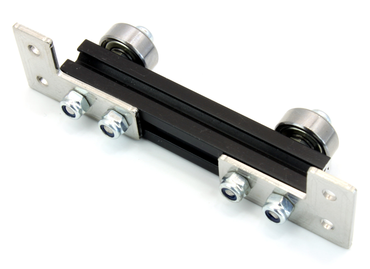
Add L-brackets to the 4-bearing assemblies:
Insert four 6mm bolts into a bearing-free-side of the MakerBeam.
Fasten two MakerBeam L-Brackets to the MakerBeam with two lock nuts each. Ensure that the L-brackets are facing away from the two adjacent bearings.
Repeat these steps for the second 4-bearing assembly.
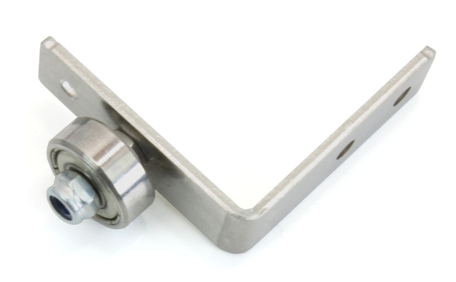
The remaining four bearings are used to lock the cart onto the frame:
Insert a 12mm bolt into a L-bracket and fasten it with a normal nut, not a lock nut.
Put a bearing onto the bolt and fasten it with a lock nut.
Repeat these steps three times to create four L-brackets with a bearing each.
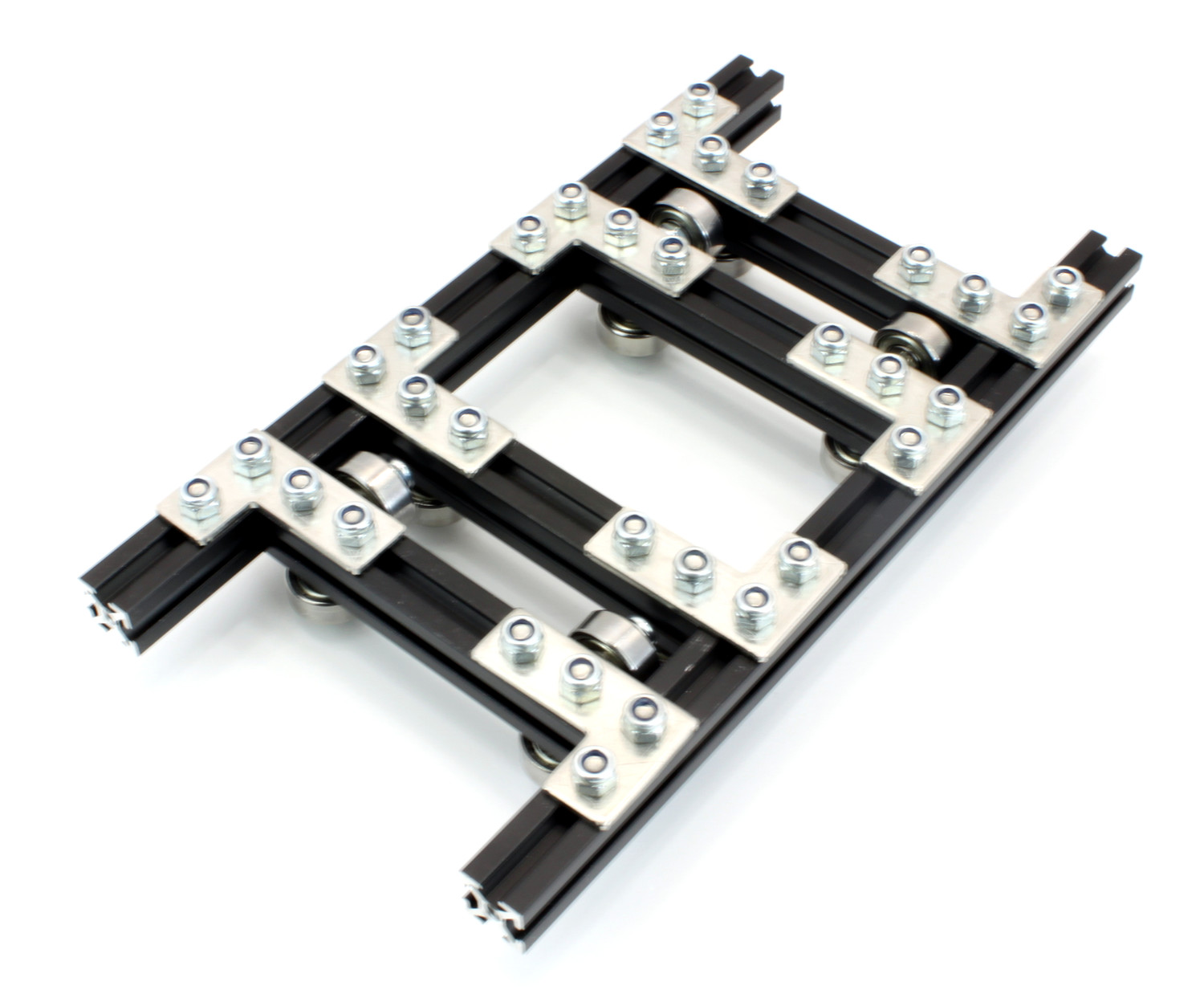
Substructure
The substructure of the cart consists of the previous build four bearing assemblies and two 150mm MakerBeams:
Insert four 6mm bolts into a 150mm MakerBeam.
Fasten a 4-bearing and a 2-bearing assembly to the MakerBeam with two lock nuts each. Ensure that the bearings on the side of the 4-bearing assembly face the 2-bearing assembly and that the L-brackets are facing away from each other.
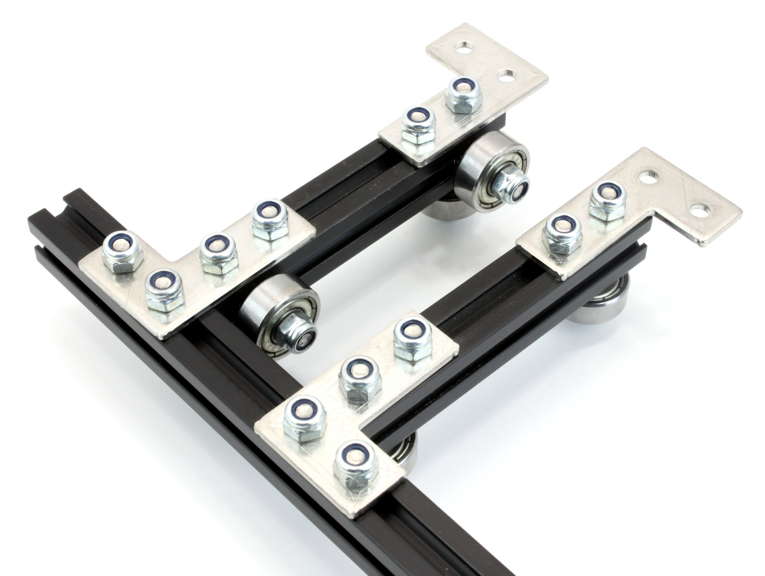
Attach the second pair of bearing assemblies the same way the first pair got attached. Then add a second 150mm MakerBeam to the cart:
Insert eight 6mm bolts into a 150mm MakerBeam.
Fasten the four bearing assemblies to the MakerBeam with two lock nuts each.
Add bolts to later attach the timing belt clamps to:
Insert two 12mm bolts in the bottom side of each 150mm MakerBeam and fasten each one near the middle of the MakerBeam with a lock nut.
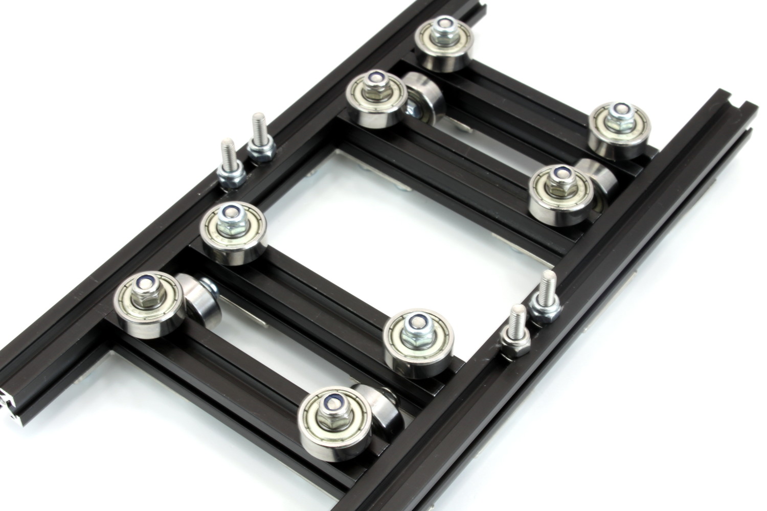
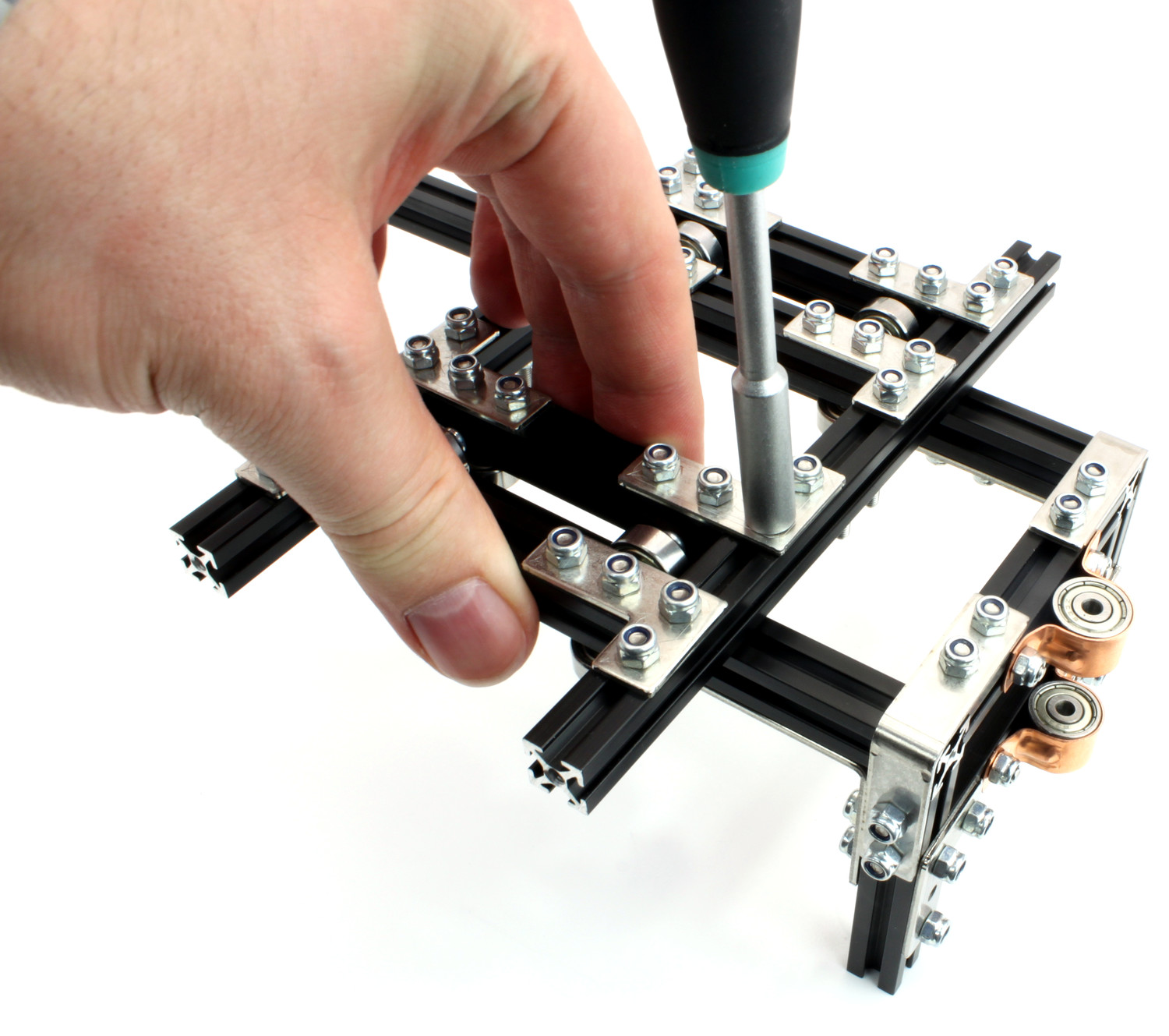
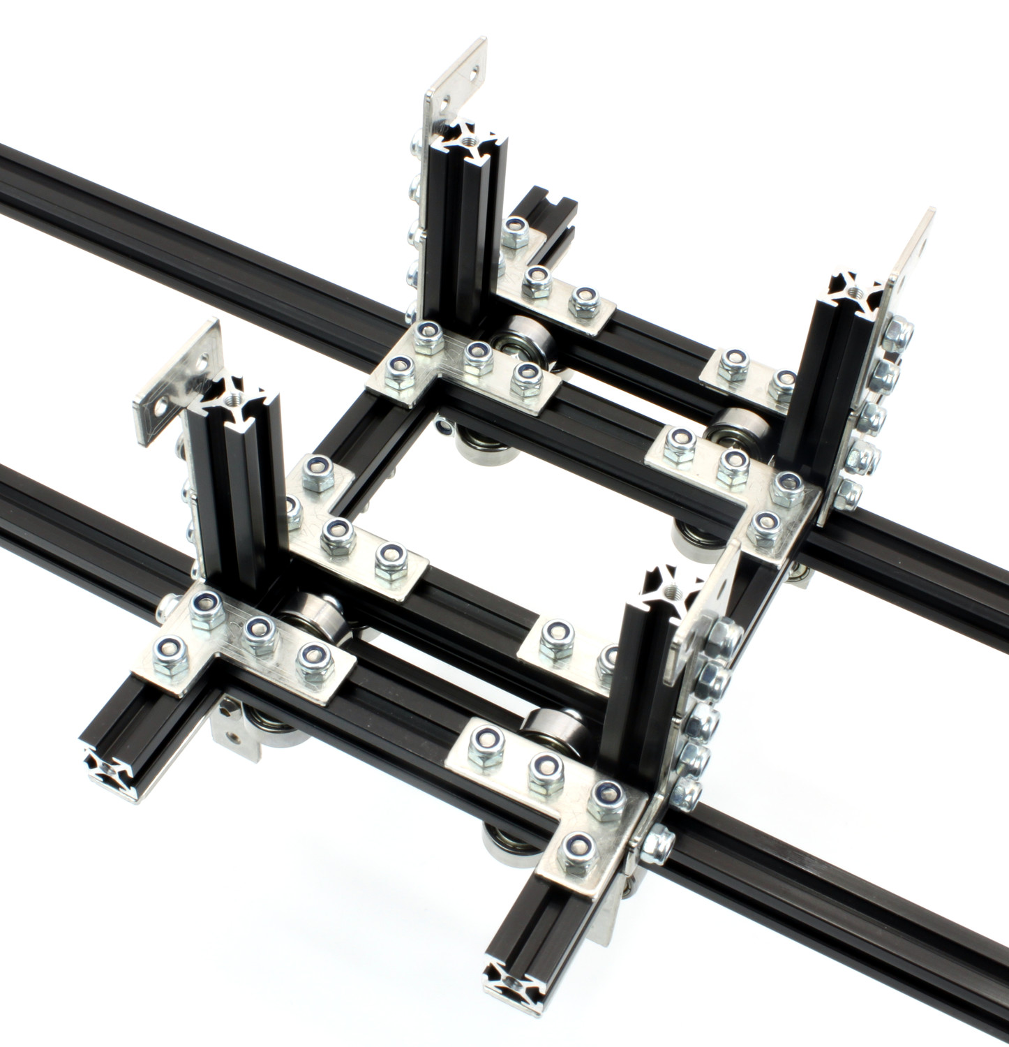
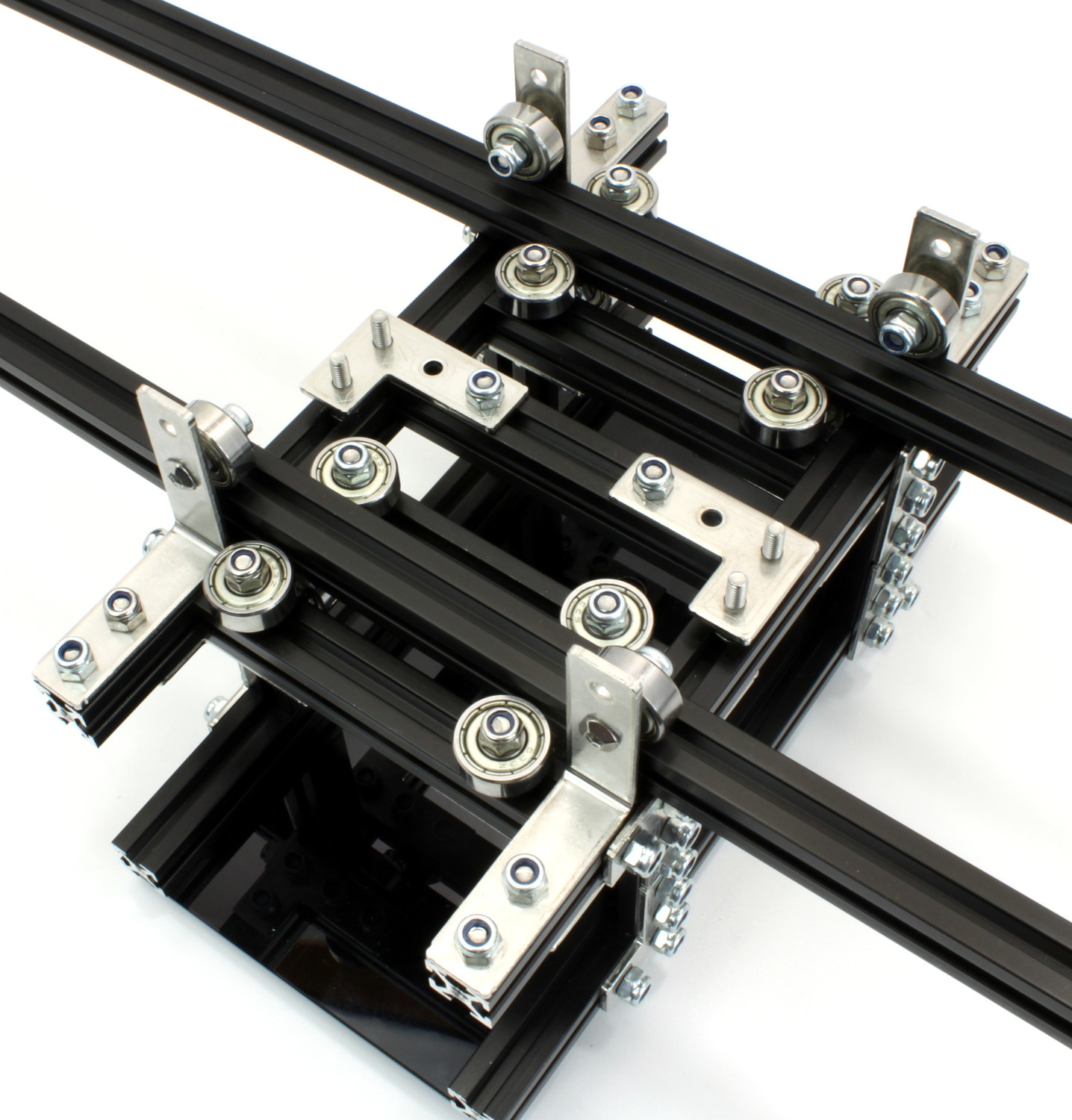
Aligning the Bearings
The bearing assemblies have to be aligned to the frame before the cart superstructure can be added:
Loosen the sixteen lock nuts that fasten the bearing assemblies to the 150mm MakerBeams to allow sliding the bearing assemblies along the MakerBeams.
Put the cart onto the frame and make the 900mm MakerBeams run between the bearings.
Press each pair of bearing assemblies against the 900mm MakerBeams then fasten the loosened lock nuts again. Ensure that the 150mm MakerBeams overhang the frame equally on both sides.
Connecting Cart and Frame
The remaining four 1-bearing assemblies are used to lock the cart onto the frame:
Insert two 6mm bolts into the bottom side of the cart.
Add a washer to each bolt.
Fasten a 1-bearing assembly to the cart with two lock nuts.
Repeat these steps for each corner of the cart.
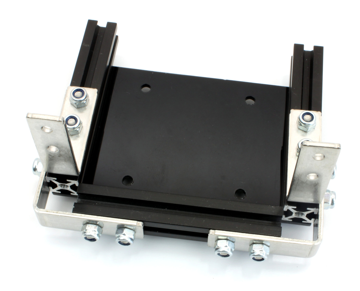
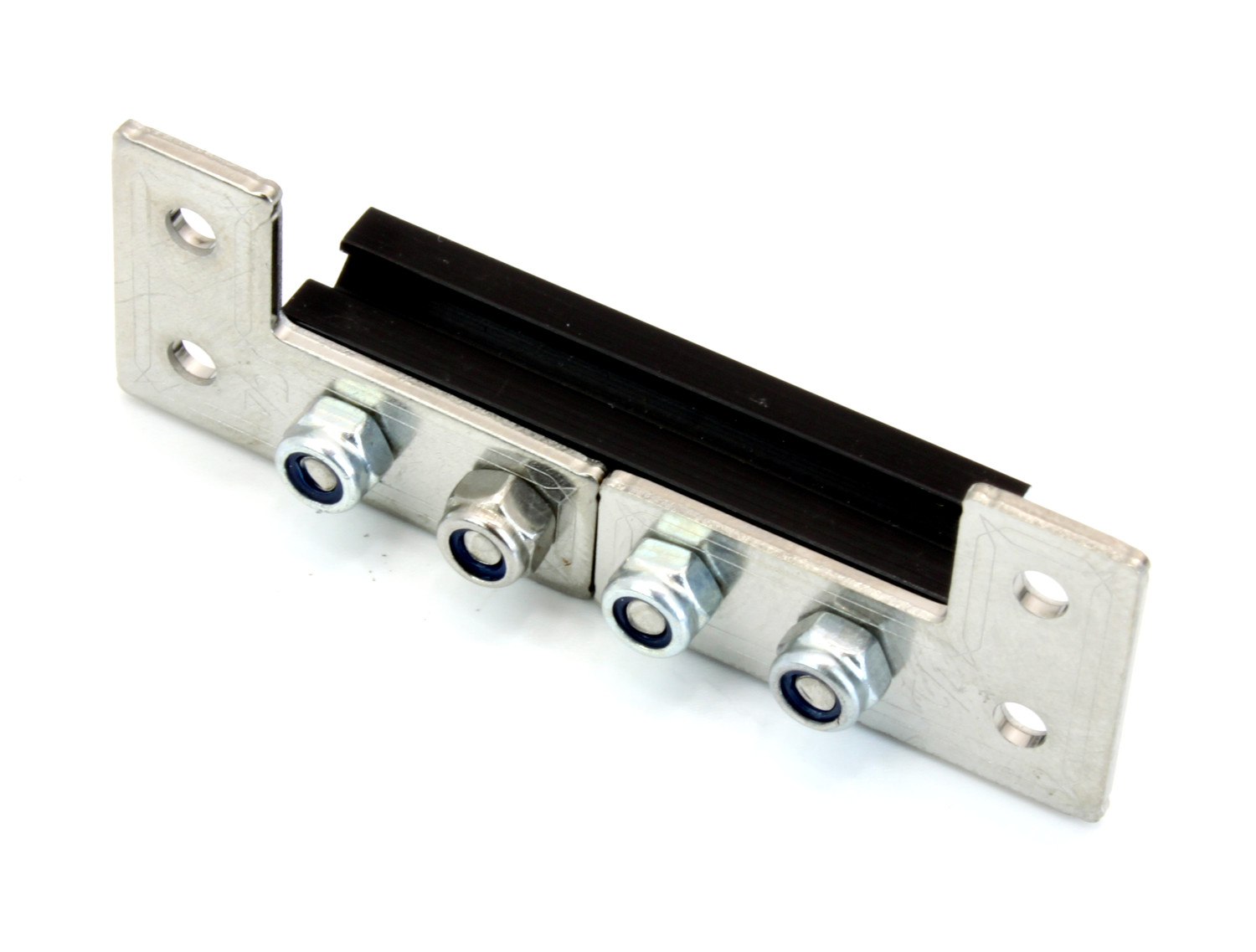
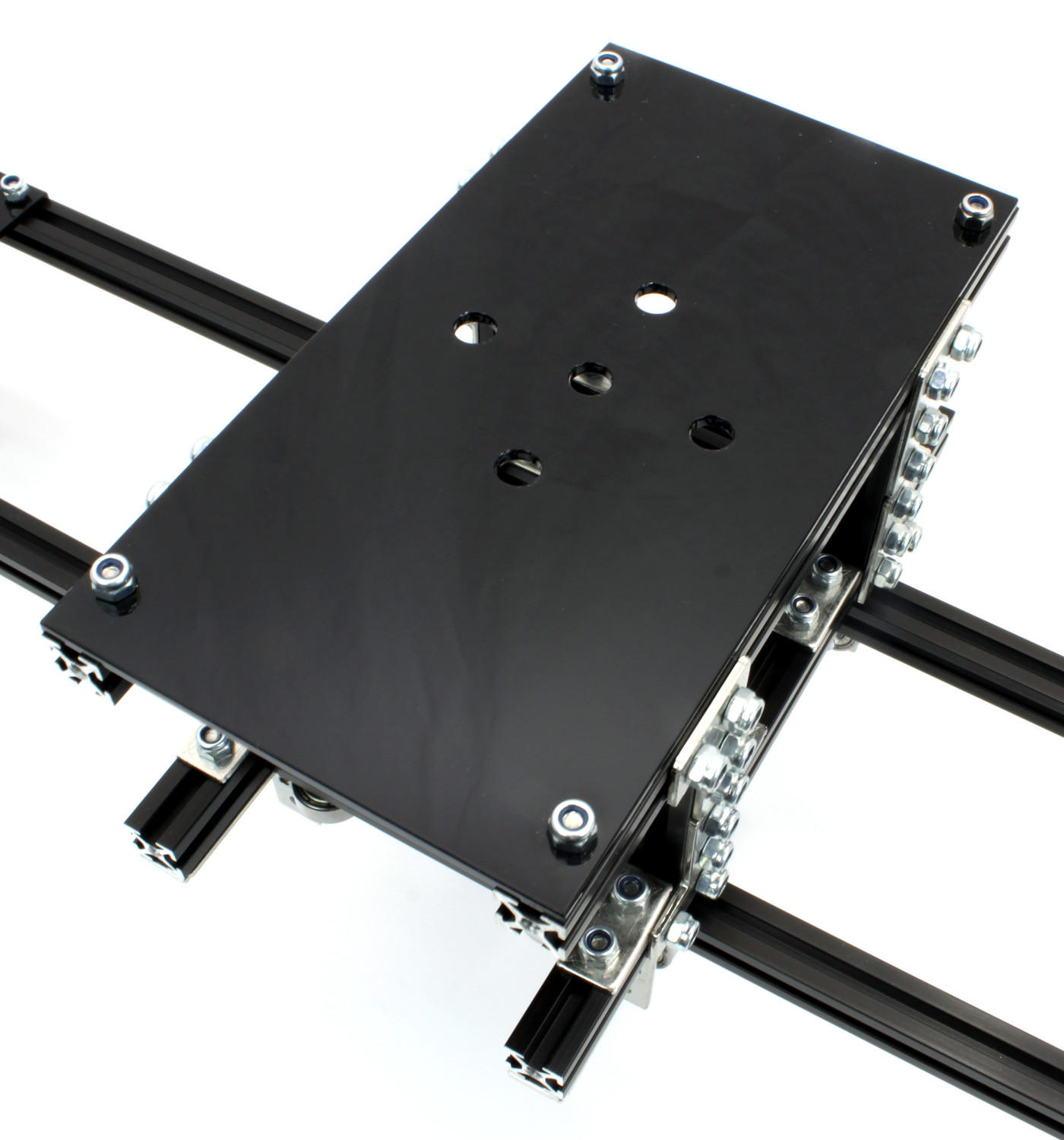
Superstructure
The camera will be mounted on top of the cart superstructure. The construction start with four corner posts:
Insert four 6mm bolts into a 40mm MakerBeam.
Fasten two L-brackets to the MakerBeam with two lock nuts each.
Repeat these steps three times to create four corner posts.
Attach the corner posts to the substructure:
Insert two 6mm bolts in the side of the 150mm MakerBeam.
Fasten a corner post to the MakerBeam with two lock nuts. Ensure that the post sits between the L-brackets of the substructure and that the L-brackets of the post are facing to the outside of the cart.
Repeat these steps for each corner post.
To complete the superstructure attach the camera bracket to it:
Insert four 6mm bolts into a 150mm MakerBeam.
Fasten the MakerBeam to two corner posts with two lock nuts each.
Repeat these steps for the other two corner posts, then attach the camera bracket:
Insert two 6mm bolts into the top of each MakerBeam.
Fasten the camera bracket to the MakerBeams with four lock nuts.
Timing Belt
In the final step of the construction the stepper motor and the timing belt are added to the camera slider.
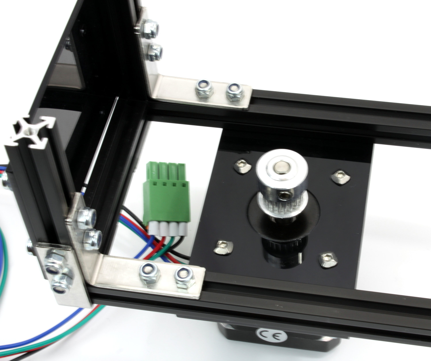
Pulleys
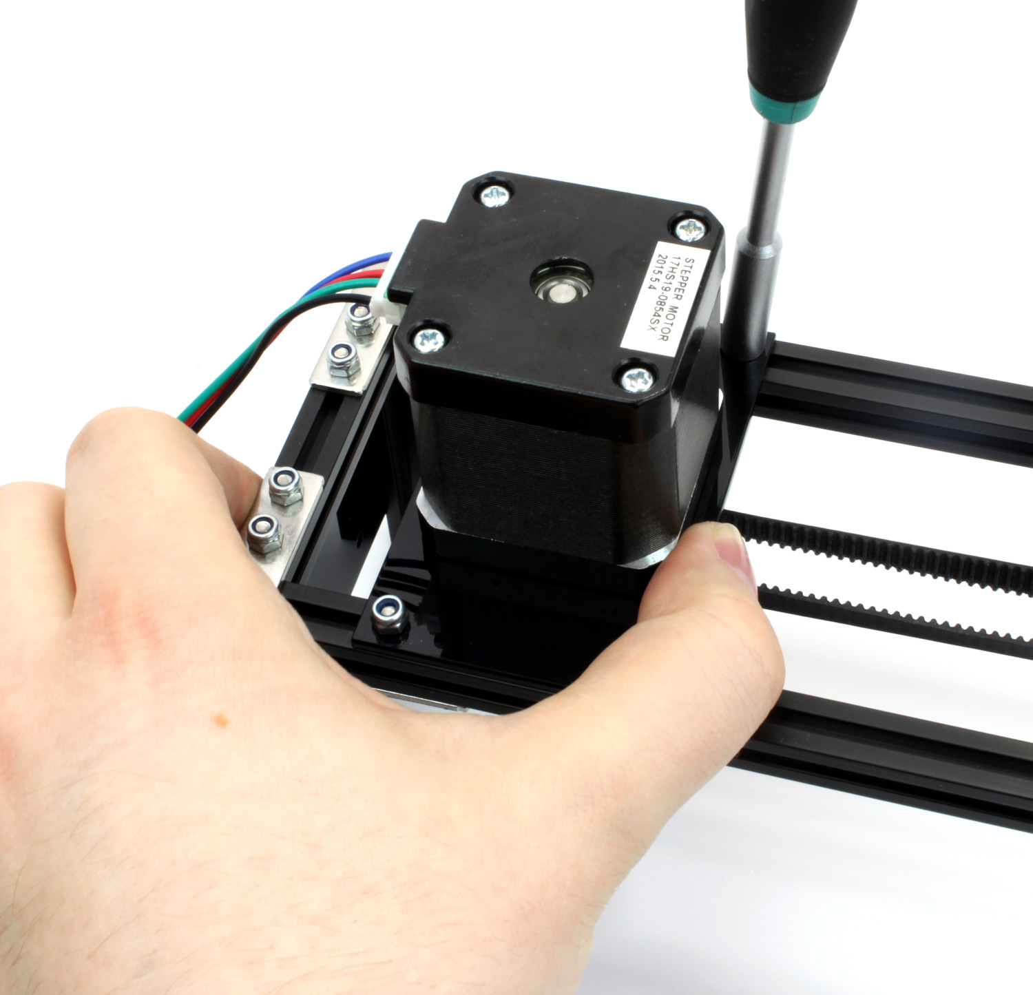
The drive pulley gets attached to the stepper motor:
Put a pulley on the stepper motor shaft. Ensure that the part with the two threaded holes faces away from the stepper motor and that it is flush with the end of the shaft.
Fasten the pulley to the shaft with two setscrews. Ensure that one setscrew sits on the flat portion of the shaft.
Fasten the stepper motor (pulley-side facing downwards) to the stepper motor bracket with four 6mm bolts.
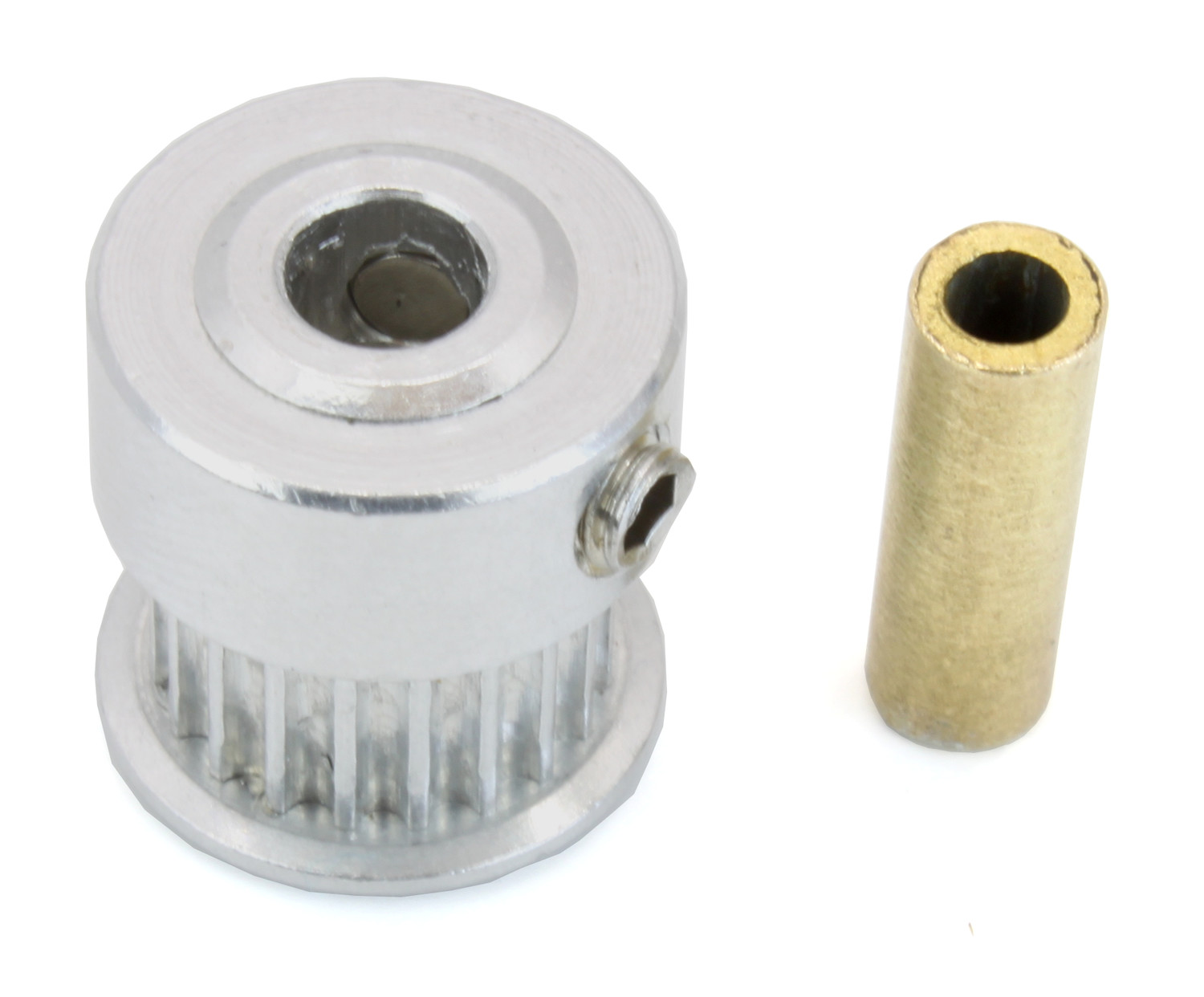
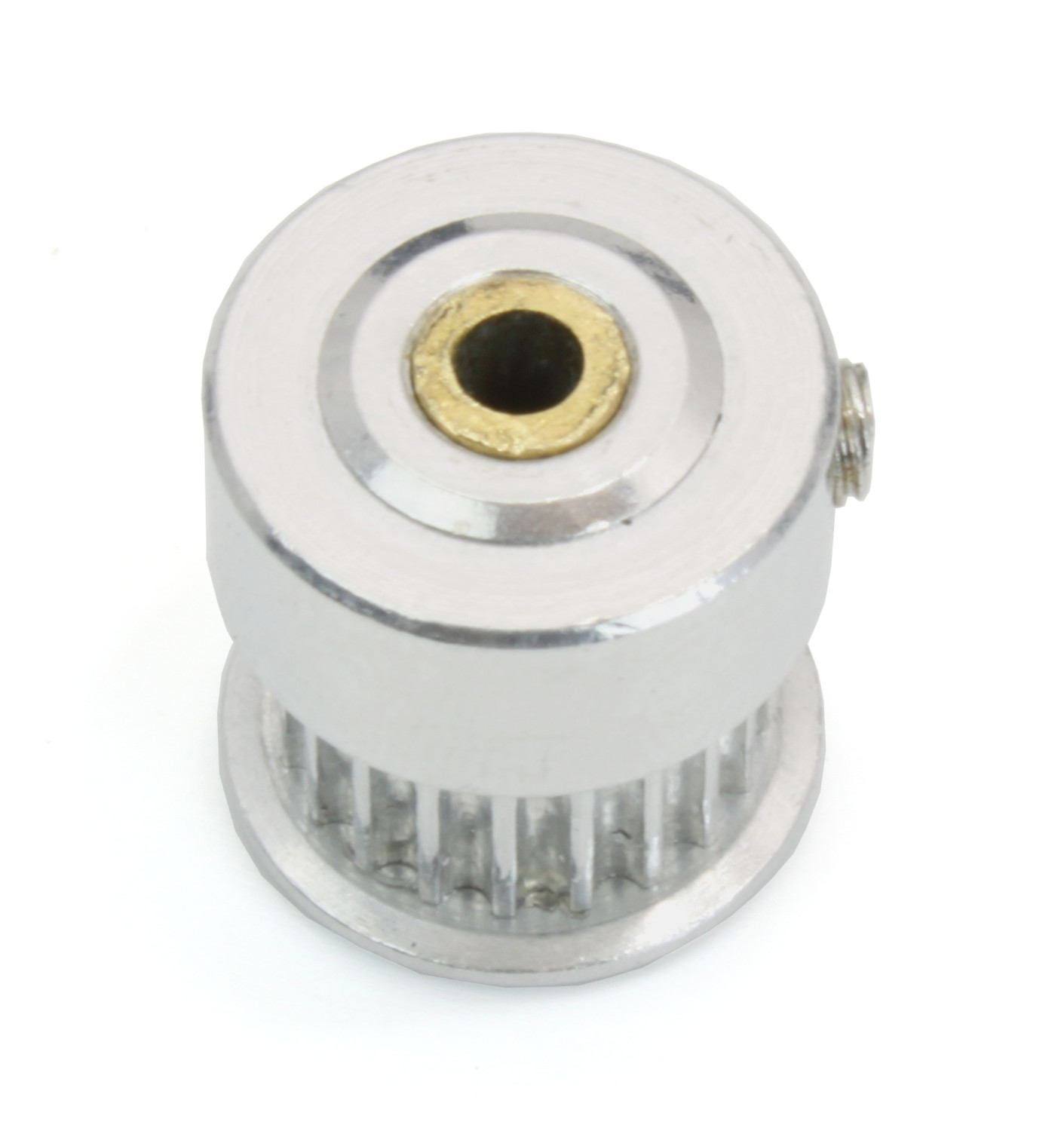
The idler pulley on the other end of the frame uses a on long M3 bolt as shaft, but the pulley has a 5mm hole. A brass shaft reducer reduces the hole to 3mm:
Put the reducer into the pulley. This is a tight fit. Ensure that the setscrews of the pulley are loose. The fit might be so tight that the reducer does not seem to fit at all. In that case use pliers, a vice, a hammer or a similar tool to apply light force to press the reducer into the pulley.
Fasten the two setscrews.
Install the modified pulley between the two bearing assemblies with a long M3 bolt. You might need to adjust the alignment of the bearings to make the bolt fit properly.
Clamps
The timing belt clamps get attached to a 60mm MakerBeam:
Insert two 6mm bolts into a 60mm MakerBeam.
Fasten two L-brackets to the MakerBeam with a lock nut each.
While the cart substructure was built, four 12mm bolts with lock nuts were added to the bottom side of the cart:
Realign those 12mm bolts so that one bolt on each side of the cart sits in the middle of the cart.
Realign the other two bolts so that the 60mm MakerBeam with the two L-brackets fits onto the four bolts. Ensure that the MakerBeam sits in the middle of the cart.
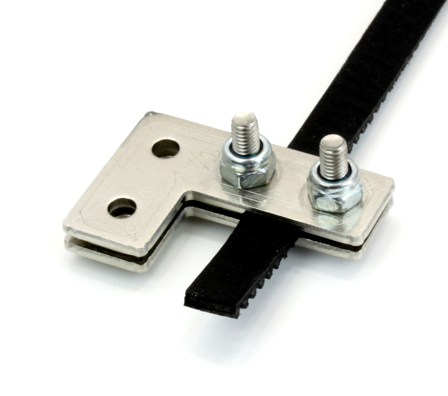
Two L-brackets form a timing belt clamp:
Connect two L-brackets with two 12mm bolts and two lock nuts.
Put one end of the timing belt between the L-brackets and fasten it with the lock nuts. Ensure that the smooth side of the belt faces in the same direction as the lock nuts and that the L-brackets face in the direction of the belt end.
Repeat these steps for the other end of the timing belt. The second clamp has to be a mirror image of the first one. Also, do not fully tighten the second clamp to be able to adjust the belt length later.
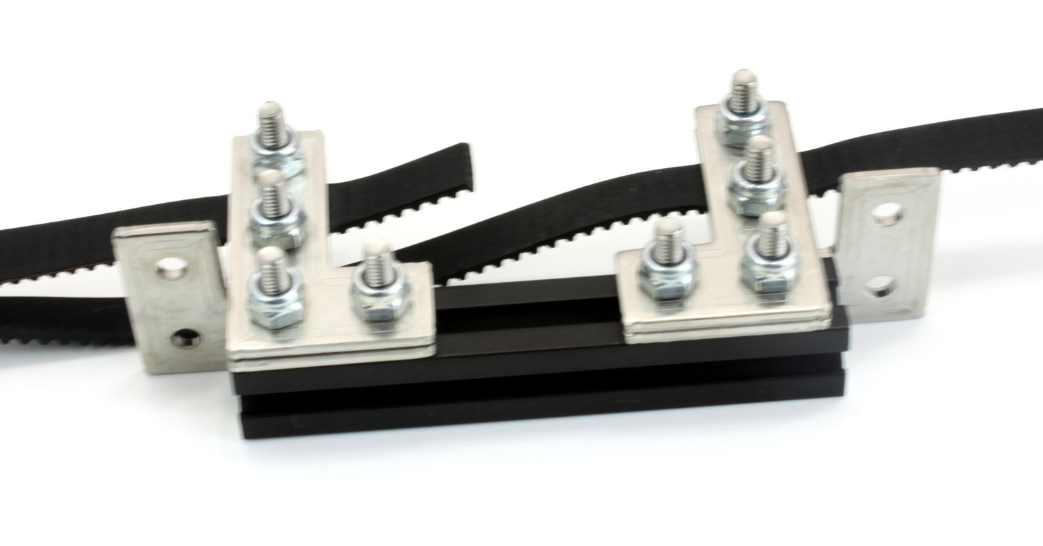
Attach the clamps to the 60mm MakerBeam:
Insert four 12mm bolts into the side of the 60mm MakerBeam.
Fasten the clamps to the MakerBeam with two lock nuts each, but do not fully tighten the second clamp to be able to adjust the belt length later. Ensure that the belt forms a loop with no twists and its smooth side facing outwards.
Put the MakerBeam-clamp assembly back into the bottom of the cart onto the four 12mm bolts and loop the belt around the drive pulley and the idler pulley. Ensure that the pulleys face downwards with their threaded hole part.
After the timing belt is installed it has to be tensioned:
Loosen the stepper motor bracket and move it to a position 1cm away from the end of the frame.
Reduce the length of the timing belt loop to remove all slack.
Fasten the second clamp that was left loose.
Tension the timing belt by pushing the stepper motor bracket towards the end of the frame.
Fasten the stepper motor bracket again.
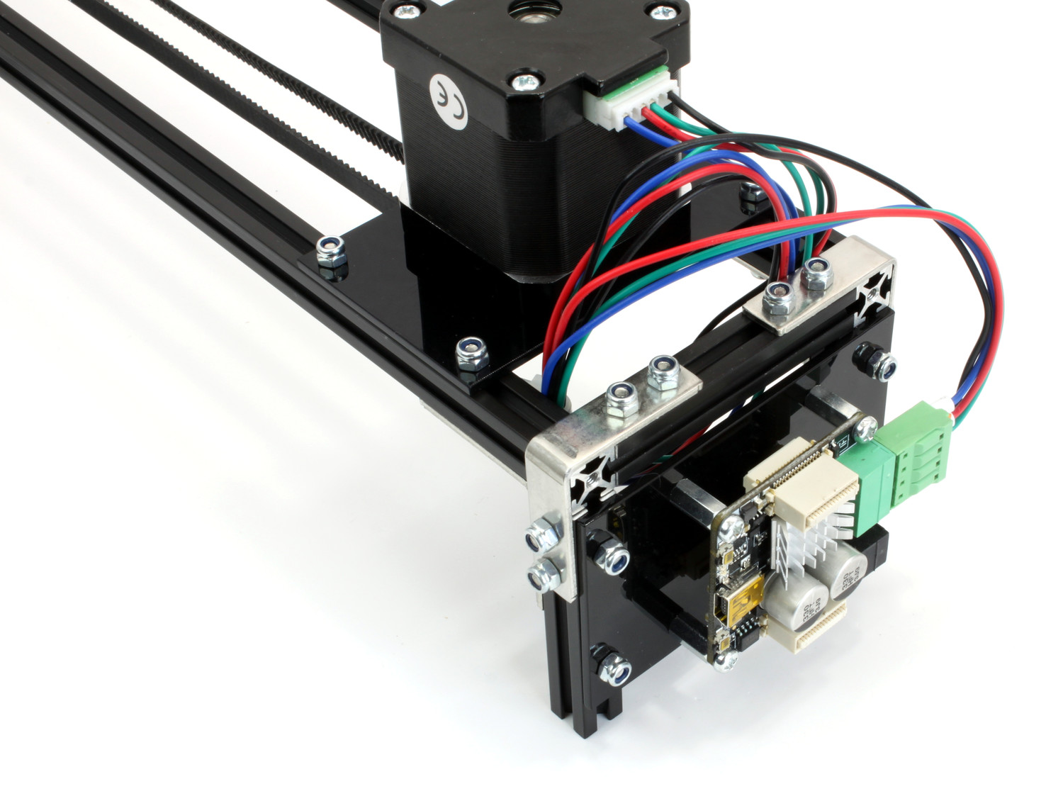
Stepper Brick
Almost done. The final step it to add the Stepper Brick and the 3D printed end caps:
Fasten the Stepper Brick to the stack bracket with four 10mm spacers and eight 6mm bolts from the Stepper Brick's mounting kit.
Put a 3D printed end cap on each leg.
Done!
The camera slider is now fully assembled. You will also have some leftover parts.