- Getting Started
- Hardware
- Software
- Kits
- Starter Kit: Weather Station
- Starter Kit: Hardware Hacking
- Starter Kit: Server Room Monitoring
- Starter Kit: Server Room Monitoring 2.0
- Starter Kit: Blinkenlights
- Starter Kit: Internet of Things
- Starter Kit: Camera Slider
- Tabletop Weather Station
- Embedded Boards
- Specifications
Remote Mains Switches Hardware Setup
This kit includes two remote control mains switches. This example describes how to hack the included remote control. There are many other remote control mains switches with similar or identical remote controls on the market. You can most likely use this description for these, too.
Most remote controls for remote control mains switches are equipped with an IC called HX2262. Basically it has six different inputs: Two to define if it is an ON or OFF switch command and four inputs to define what it switches (A, B, C or D). An input is activated if it is switched to GND. All inputs are interconnected in a matrix style order.
In this example we will use the Industrial Quad Relay Bricklet with its four solid state relays to short the inputs ON, OFF, A and B to GND. This way we will be able to switch two remote switches. If you want to also switch C and D, you can use an additional Industrial Quad Relay Bricklet.
The innards of the Remote Control
If you open your remote control you will see a circuit board like this (how-to video 1:31):
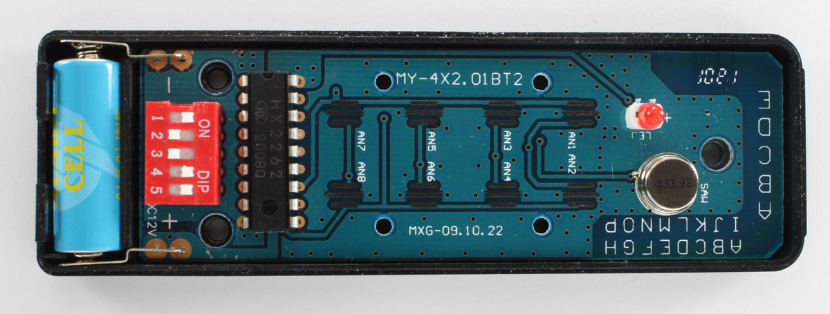
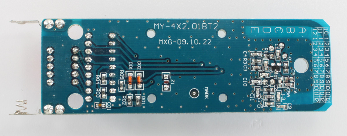
The big IC right of the red DIP switch is the HX2262. If you remove the casing completely and take a look at the bottom side it should look like this:
Solder wires to the IC
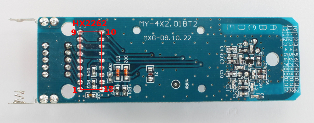
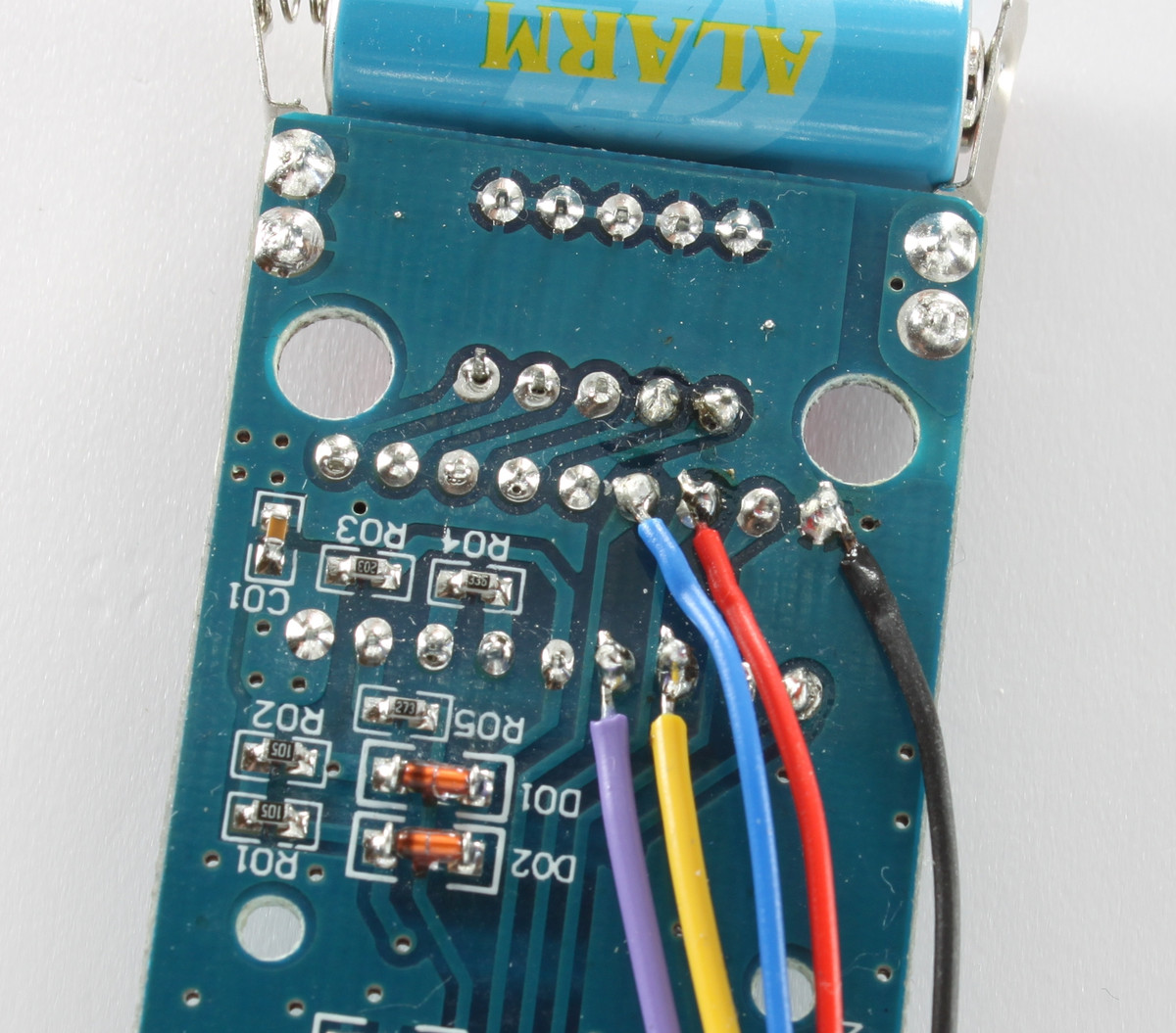
Next we have to solder the wires to the HC2262 to connect to the inputs of the remote control. We will solder five wires to the HX2262 IC (Small soldering tutorial, how-to video 1:56):
Pin Number |
Signal |
Wire Color |
|---|---|---|
6 |
A |
blue |
7 |
B |
red |
8 |
C |
/ |
9 |
GND |
black |
10 |
D |
/ |
11 |
/ |
/ |
12 |
ON |
yellow |
13 |
OFF |
purple |
The following image depicts the position of the HX2262 and the pin numbering:
After soldering it will look like this:
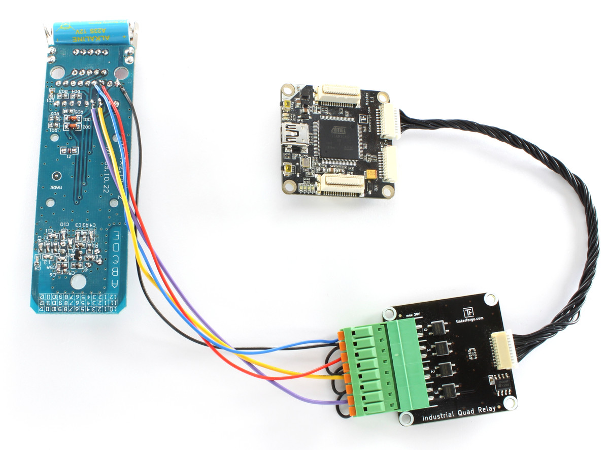
Connect wires to the Industrial Quad Relay Bricklet
Next we will connect these wires (except black) to the Industrial Quad Relay Bricklet. Each input of the HX2262 is connected to its own relay. Simply put it into one of the two connectors of a relay (how-to video 4:30).
Signal |
Wire Color |
Relay |
|---|---|---|
A |
blue |
0 |
B |
red |
1 |
ON |
yellow |
2 |
OFF |
purple |
3 |
Now every Relay is connected to one wire, but each relay is missing the second wire. Since we want to switch to GND, the second connection has to be to GND. So we have to connect the black GND wire to all of them. We do this by connecting the black wire to one relay and the other relays will be connected to it by small wires we create of the second black wire (how-to video 5:02). The next picture depicts the finished work.
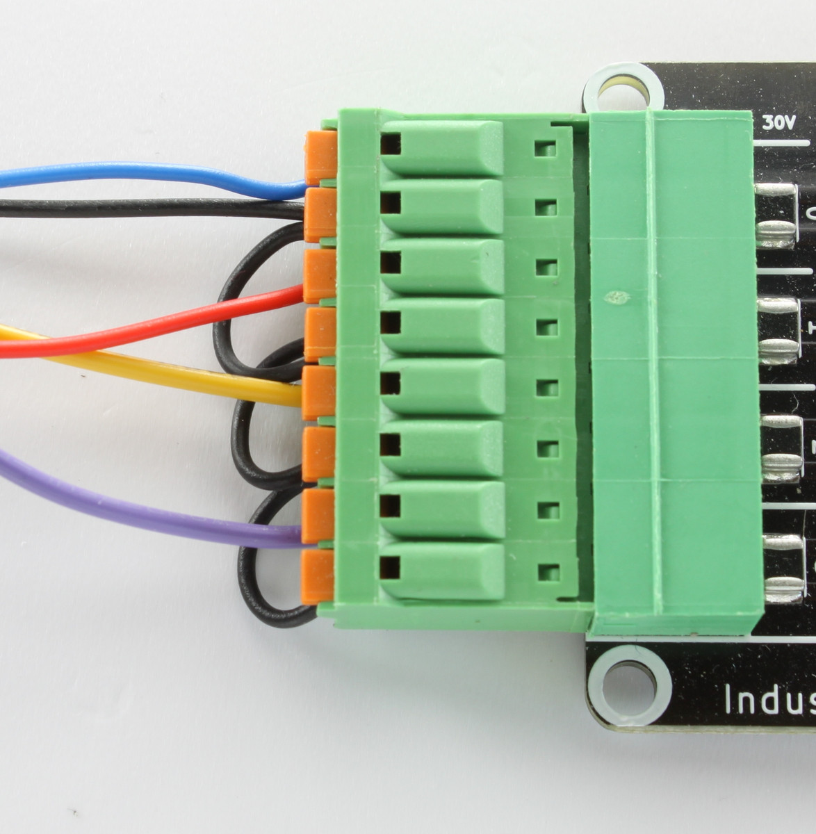
After that we are finished. The full hardware setup will look like this: