- Getting Started
- Hardware
- Software
- Kits
- Starter Kit: Weather Station
- Starter Kit: Hardware Hacking
- Starter Kit: Server Room Monitoring
- Starter Kit: Server Room Monitoring 2.0
- Features
- Description
- Technical Specifications
- Resources
- First tests, firmware upgrade and configuration
- Construction
- RED Brick
- Raspberry Pi + HAT Brick
- Projects
- Further Enhancements
- Starter Kit: Blinkenlights
- Starter Kit: Internet of Things
- Starter Kit: Camera Slider
- Tabletop Weather Station
- Embedded Boards
- Specifications
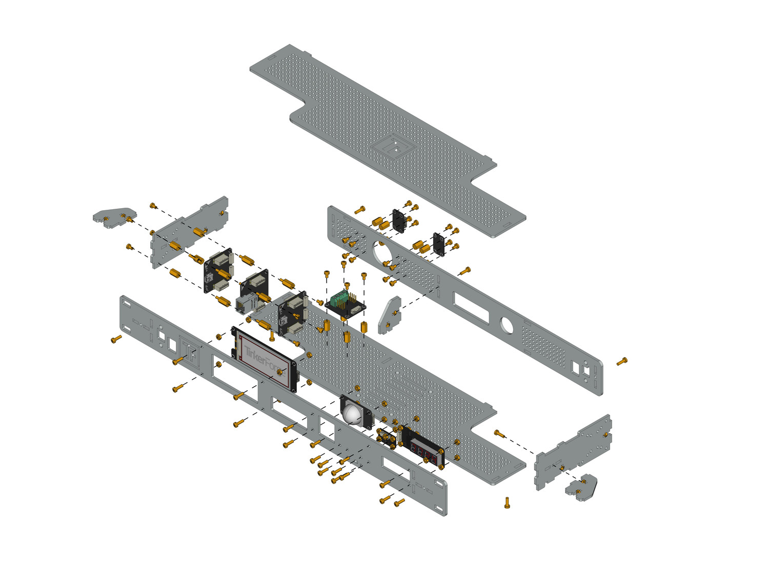
Construction of Starter Kit: Server Room Monitoring 2.0
The Starter Kit: Server Room Monitoring 2.0 comes with
and Bricklet cables as well as lots of screws, spacers, nuts and washers.
Screws, spacers, nuts and washers are packed in mounting kits. These are standardized kits and are not specially composed for this starter kit. Get the necessary parts you need for each step from all mounting kits. The remaining mounting parts can be used for your own modifications.
Remove Protective Foils
At first the protective foils on all case parts have to be removed. There is a foil on the front and back side. In some cases the protective foils may be hard to remove, you can use a cutter or similar as a lever to get to the foil.
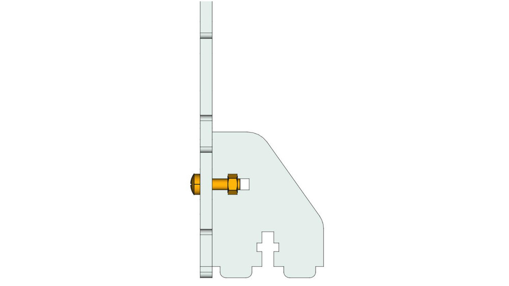
Screw Brackets to Side Parts
As the first construction step screw one bracket to one side part each. To do this you have to put a nut in the dedicated slot of the bracket, put a 12mm long screw through the side part and fix the bracket. If the nut does not seem to fit, rotate it a little bit in the slot until it fits.
The result is depicted in the following image:
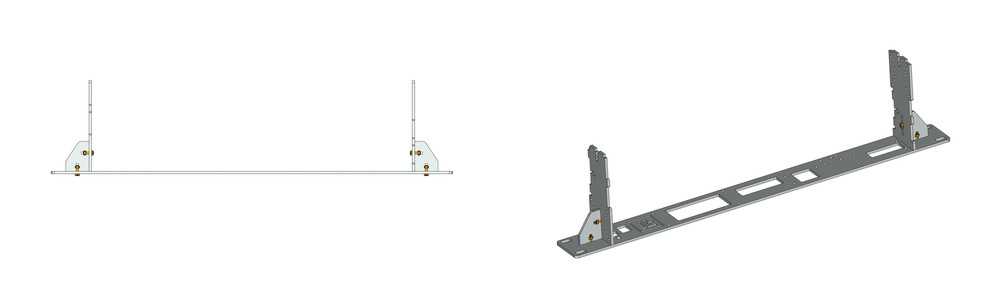
Screw Side Parts to the Front Panel
Attach the previously build side parts into the front panel and screw it to the front panel with the same nut technique. Attach the front panel as depicted in the following image (pay attention to the direction of Tinkerforge Logo).
Screw Back Side to the Side Parts
Next take eight 10mm spacers (thread inside/inside) and short screws and attach them to the position of the Temperature and Humidity Bricklet.
Put the back side on the side parts and attach it with nuts and screws. Additionialy you have to put a Bracket in the middle of the back. Pay attention that the bottom plate can be attached as described in the next step.

Attach Bottom Plate
Attach the bottom plate to the back side of the sideplates and fix it as usual with 12mm screws and nuts. After this take four 10mm spacers (thread inside/inside) and short screws and attach them to the desired position for the PTC Bricklet 2.0. After that you have completed the build of the rack enclosure. In the next step we attach the Bricks and Bricklets to it.
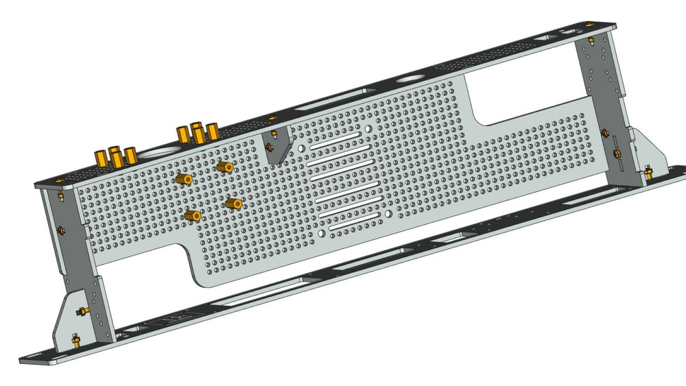
Attach Bricks and Bricklets
Now the Bricks and Bricklets will be attached to the case.
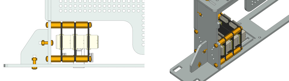
Master Brick and Ethernet Extension
Use four 12mm spacers (thread inside/outside) and put them between Master Brick and Ethernet Extension (on top). Fix them with 10mm spacers (thread inside/inside) and washers on the bottom side and with screws on the top side of the Ethernet Extension.
Screw this stack to one of the side parts by four screws. If you need the connectors in front take the mounting holes of the left side plate. If you want to put the cables at the back you have to use the holes of the right side plate.
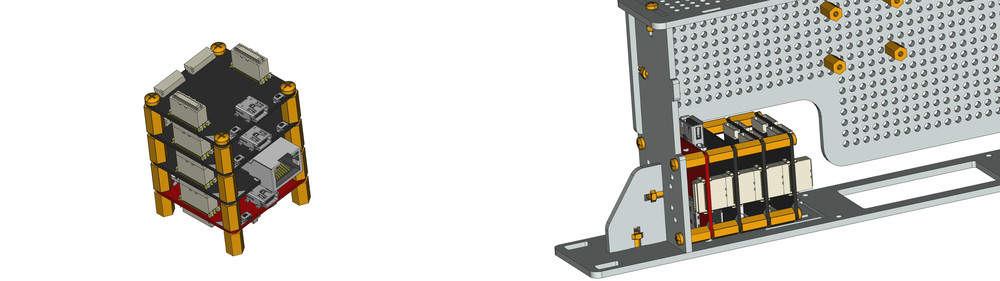
RED Brick (optional)
If you build the kit including a RED Brick, you have to put the RED Brick in place of the Master Brick and the Master Brick on top of the Ethernet Extension. Each can use the 12mm spacers (thread inside/outside) and washers.
Raspberry Pi und HAT Brick (optional)
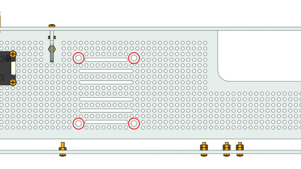
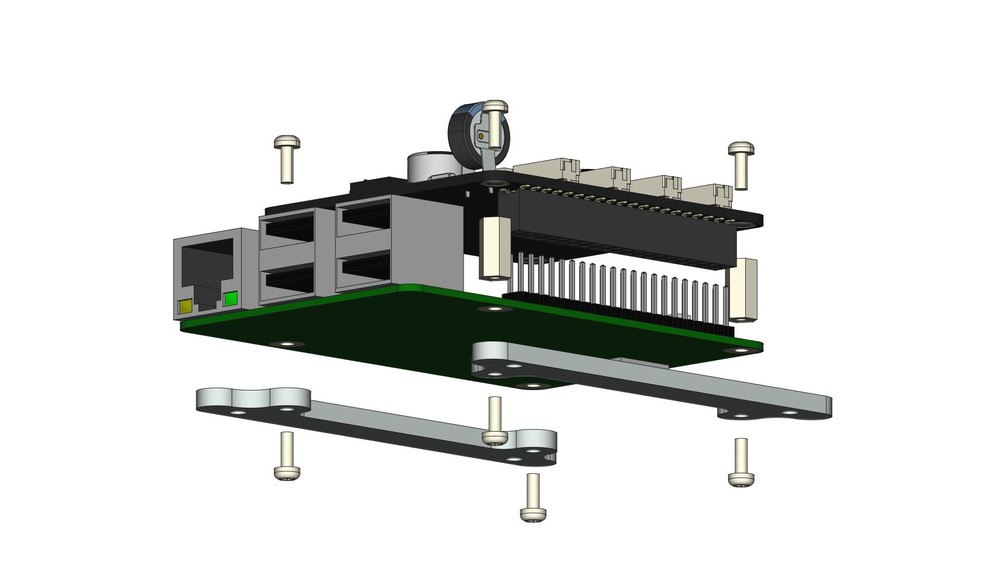
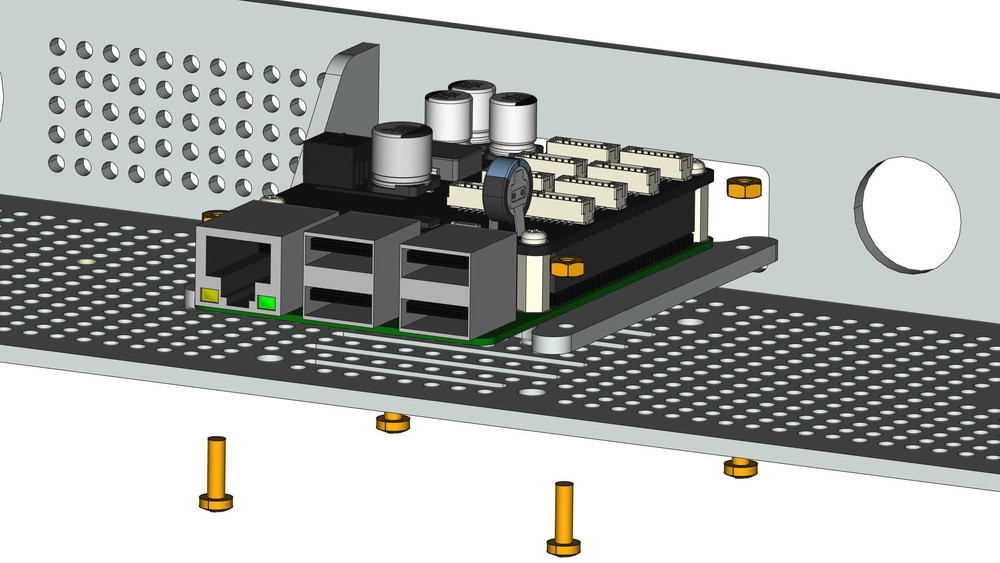
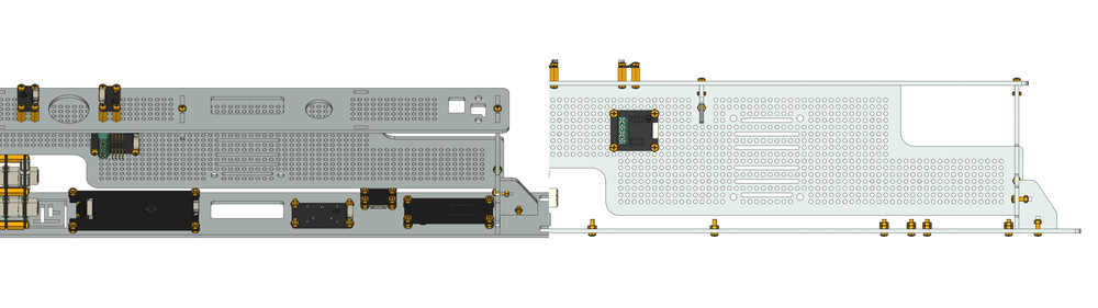
Fot the usage with your Raspberry Pi you have to attach it together with the HAT Brick to the middle of the bottom plate. For this you need the Raspberry Pi Mounting Kit. There are two mounting bars which have to be screwed to the Raspberry Pi. After that you can mount it to the bottom. The botton has holes for this step that you can use to attach it. Mount it with long screws and nuts. In this step you can mount the Raspberry Pi either forward or backward, depending on your preference.
PTC, Temperature and Humidity Bricklet
Next attach the Temperature Bricklet 2.0 and the Humidity Bricklet 2.0. Use four screws to mount them on the previously installed spacers on the back side part and the PTC Bricklet 2.0 on spacers on the bottom plate.
Before the first usage the PTC Bricklet 2.0 has to be configured and the temperature probe (2-wire) has to be attached. How this is done is documented here and here.
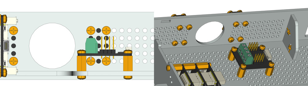
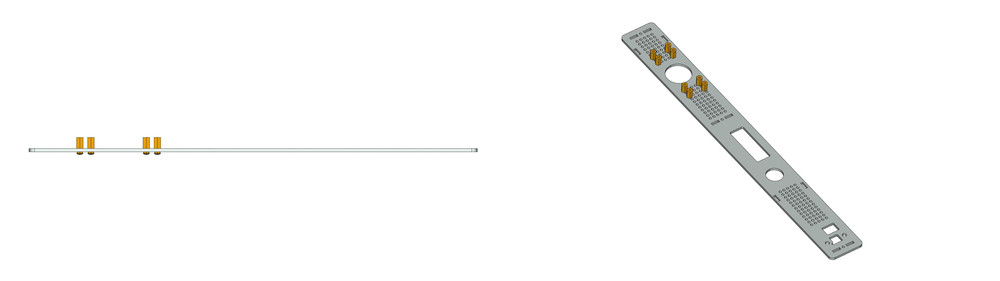
E-Paper, Segment Display, Ambient Light Bricklet
Attach the Ambient Light Bricklet 3.0, Segment Display 4x7 Bricklet 2.0 and the E-Paper 296x128 Bricklet (schwarz/weiß/rot) to the front panel. After that put 12mm long screws through the front panel and fix them with two nuts each. For the E-Paper just take one nut for each screw. Then connect the 50cm Brickelt Cable to the Brickelts. After that put the Bricklets on the scews and attach them with four additional nuts.
Connect Cables, Attach Cover and Done
As the last step connect the Bricklet cables to the Master Brick and use a cable strap to fasten them.
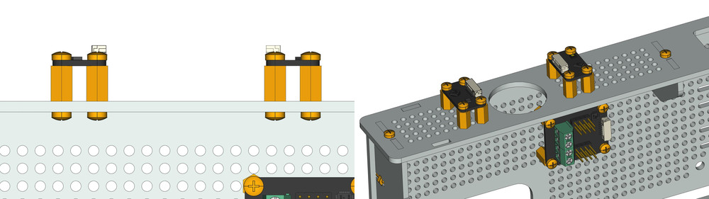
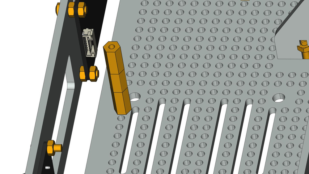
Afer you are done with the cabling put three spacers together and place them near the front panel, as seen in the following picture, and attach them with a screw on the bottom plate. Then put the cover on it and attach one last screw.
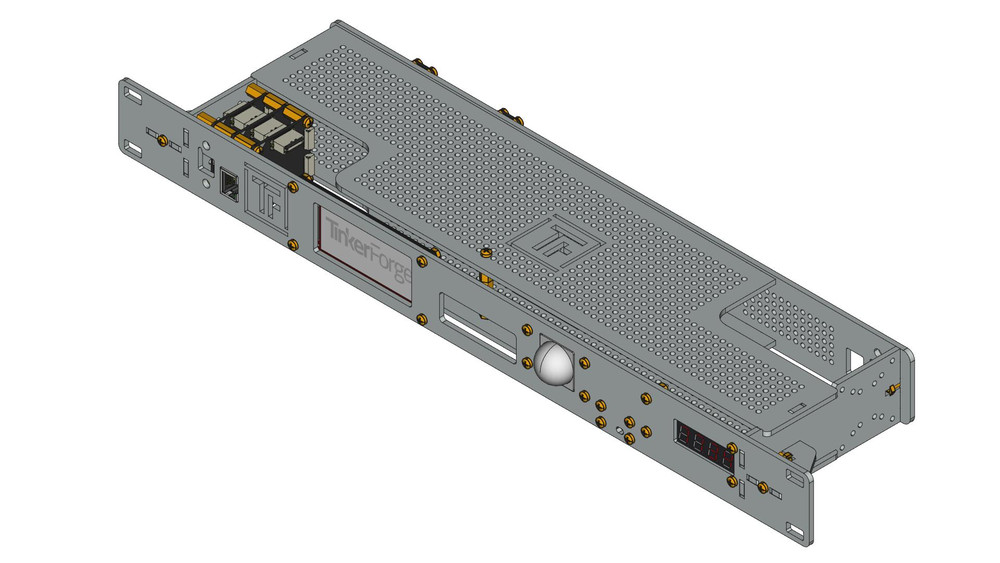
That's it! The finished work should look as the following: