- Getting Started
- Primer
- Tutorials
- First Steps
- Rugged Approach
- Authentication
- RED Brick
- Build Environment Setup
- Bricklet Cables (7 pole vs 10 pole)
- ESP32 Firmware
- FAQ
- Downloads
- Hardware
- Software
- Kits
- Embedded Boards
- Specifications
Tutorial - ESP32 Firmware
The ESP32 Firmware is a modular firmware and utilizes PlatformIO. This tutorial explains how the ESP32 firmware can be extended by your own module. As an example we build a module which interacts with a RGB LED Button Bricklet. As editor Visual Studio Code is used.
First the ESP32 firmware setup to build the standard firmware has to be prepared. Please follow the steps of the ESP32 Firmware documentation.
All paths and file names in this tutorial are related to the software/
directory of the ESP32 firmware. Also make sure to open the software/
directory in Visual Studio Code as the PlatformIO project directory.
This tutorial consists of five phases. Each stage of expansion of the new module are already included at the ESP32 firmware but not used. We explain these stages in the following step by step.
A ESP32 Brick and the ESP32 Ethernet Brick
can be used for this tutorial. The only difference between these two Bricks is the
.ini file that will be modified during this tutorial:
ESP32 Brick:
esp32.iniESP32 Ethernet Brick:
esp32_ethernet.ini
To enable the respective stage the name of it
has to be added at the end of the custom_backend_modules, custom_frontend_modules
and custom_frontend_components options.
After that the firmware has to be build and uploaded to the Brick by "Upload and Monitor"
in Visual Studio Code.
Phase 1: Create empty module
Append Tutorial Phase 1 in file esp32.ini or esp32_ethernet.ini as mentioned above
at the end of backend and frontend modules section.
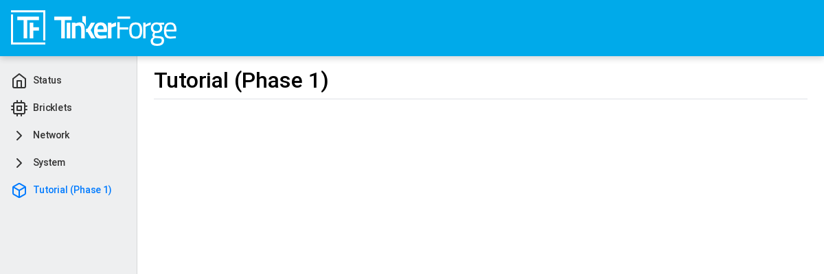
After building and uploading the project again this module shows up in the webinterface as "Tutorial (Phase 1)":
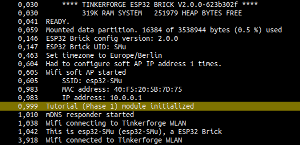
At the serial console the status message Tutorial (Phase 1) module initialized
will show up:
Modules are seperated in two different groups:
Backend: These modules are part of the firmware and has to be programmed in C/C++. Backend modules provide the actual functionality and can communicate with hardware. Backend modules can be found at:
src/modules/Frontend: These modules are part of the webinterface and has to be programmed in HTML/Sass/TypeScript. Frontend modules provide the user interface and can communicate with backend modules. Frontend modules can be found at:
web/src/modules/
Typically modules appear in backend/frontend pairs. But this is not mandatory. It is possible that there are backend modules without corresponding frontend modules and vice versa.
The module name in esp32.ini or esp32_ethernet.ini deviates the directory name of the module.
Tutorial Phase 1 lead to tutorial_phase_1 (all letters will be converted to lowercase
and spaces will be converted to underscores).
Files of a Backend Module
Each backend module will be represented by a C++ class. The name of this class
is deviated by the module name. Tutorial Phase 1 will lead to
TutorialPhase1 (all spaces removed).
The backend module class has to be declared in a header file. The name of this file has to be
the name of the module directory appended by .h. For our example the name
of the header file is tutorial_phase_1.h.
All other files in the module directory which ends with .cpp, .c or .h
will be compiled with the firmware independent of their file names.
Files of a Frontend Module
Each frontend module can contain the following files (optional):
api.ts: TypeScript definition of the backend API used by the frontend module.
main.tsx: TypeScript code of the Preact component for this module.
translation_de.json: German text translations.
translation_en.json: English text translations.
Phase 2: Communication from Backend to Frontend
Module name for esp32.ini or esp32_ethernet.ini file is: Tutorial Phase 2
(change backend and frontend entry from Phase 1 to Phase 2).
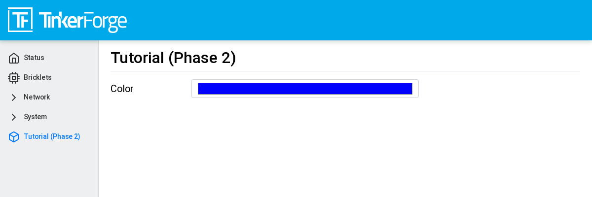
When this module is activated a subwebsite named "Tutorial (Phase 2)" will show up which contains a color view:

The shown color on this site is determined by the backend module and communicated to the frontend module. Here is how this is done:
Backend Communication Part
The backend module represent the data which should be communicated to the frontend
module. These data are structured as a ConfigRoot object. In our case it is only
one element named color which has a string with exactly 7 byte length. With that
we can describe the color in HTML notation #RRGGBB. The value #FF0000 describes
color red. This is the corresponding part of tutorial_phase_2.cpp:
void TutorialPhase2::pre_setup()
{
    config = Config::Object({
        {"color", Config::Str("#FF0000", 7, 7)}
    });
}
To communicate the color to the frontend module, the ConfigRoot object has to be
published to the API manager. To do that the name tutorial_phase_2/config will be used.
API manager automatically polls ConfigRoot every 1000 milliseconds and sends it data to the
frontend module. This is the corresponding part of tutorial_phase_2.cpp:
void TutorialPhase2::register_urls()
{
    api.addState("tutorial_phase_2/config", &config);
}
Frontend Communication Part
In file api.ts the structure of the data which should be received from the backend is
specified:
export interface config
{
    color: string
}
In file main.tsx a event listener for the state of tutorial_phase_2/config
is created, to allow the Preact component to receive value changes from the API manager.
Inside the lambda function the current value of the tutorial_phase_2/config state
is received and the contained color value color is saved in the state of the
Preact component:
util.addApiEventListener('tutorial_phase_2/config', () => {
    let config = API.get("tutorial_phase_2/config");

    this.setState({color: config.color});
});
Communication Test
To test the communication the color value in tutorial_phase_2.cpp can be changed
from #FF0000 (red) to #0000FF (blue):
 void TutorialPhase2::pre_setup()
 {
     config = Config::Object({
         {"color", Config::Str("#0000FF", 7, 7)}
     });
 }
Now in the webinterface blue should be shown:
Phase 3: Communication from Frontend to Backend
Module name for esp32.ini or esp32_ethernet.ini file is: Tutorial Phase 3
When this module is active in the webinterface a subwebsite named "Tutorial (Phase 3)" shows up:

The color now can be changed by a color selection dialog.
Frontend Communication Part
In main.tsx the code reacts to the change event of the HTML element. On change
the current color value of the HTML element is mapped to a new value of
tutorial_phase_3/config and transfered to the backend module:
<input class="form-control" type="color" value={this.state.color} onChange={(event) => {
    let config = {color: (event.target as HTMLInputElement).value.toString()};

    API.save("tutorial_phase_3/config", config, __("tutorial_phase_3.script.save_config_failed"));
}} />
Backend Communication Part
The backend module represents the data which could be received from the
frontend module, structured as a ConfigRoot object. This object is simply
a copy of the config_update of the first ConfigRoot object,
since it has the same structure. This is the relevant part of tutorial_phase_3.cpp:
 void TutorialPhase3::pre_setup()
 {
     config = Config::Object({
         {"color", Config::Str("#FF0000", 7, 7)}
     });

     config_update = config;
 }
To receive the color value from the frontend module a second ConfigRoot object
has to be announced to the API Manager as a command. To do that the name
tutorial_phase_3/config_update is used. API Manager receives the data from the
frontend module and call a lambda function to handle the data. A message will be printed
in the serial console and a new color is saved. This is the relevant part of tutorial_phase_3.cpp:
 void TutorialPhase3::register_urls()
 {
     api.addState("tutorial_phase_3/config", &config);

     api.addCommand("tutorial_phase_3/config_update", &config_update, {}, [this]() {
         String color = config_update.get("color")->asString();

         logger.printfln("Tutorial (Phase 3) module received color update: %s", color.c_str());
         config.get("color")->updateString(color);
     }, false);
 }
Communication Test
As a test the color value can be changed from #FF0000 (red) to
#00FF00 (green) in the webinterface:
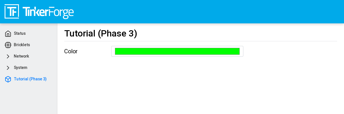
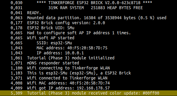
You will find the following message in the serial console:
Tutorial (Phase 3) module received color update: #00ff00
Phase 4: Communication Backend to Bricklet
Module name for esp32.ini or esp32_ethernet.ini file is: Tutorial Phase 4
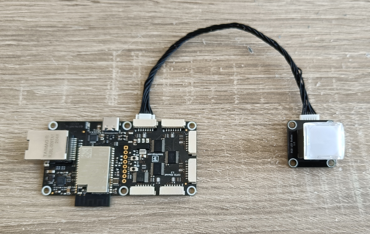
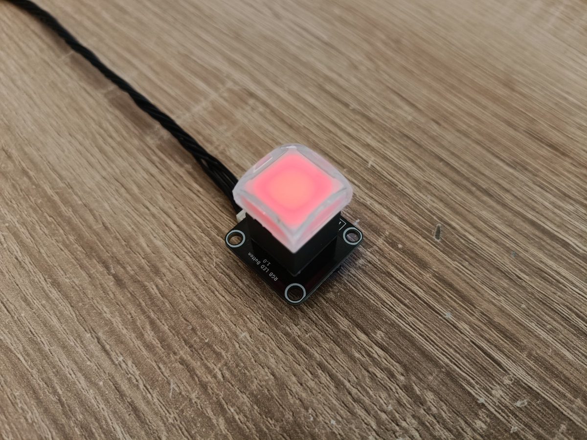
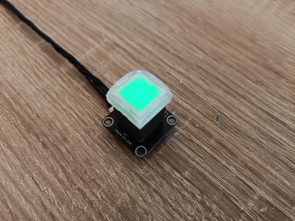
Now you have to connect a RGB LED Button Bricklet to your Brick. You can choose which Bricklet connector you use at the Brick.
After activating this module a subwebsite with a color view will show up named "Tutorial (Phase 4)":
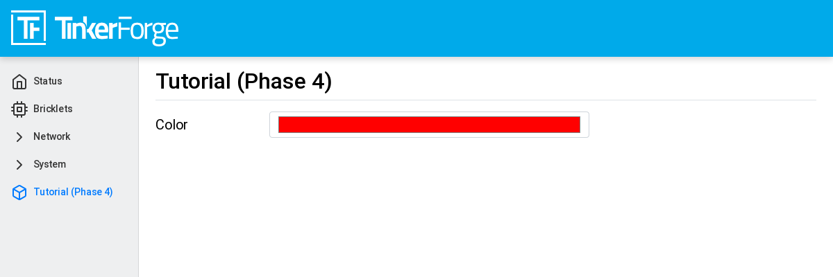
Color can be changed on this website and will be communicated to the backend module which will send it to the RGB LED Button Bricklet.
Communication frontend to backend was not changed. Now we will add the backend to
RGB LED Button Bricklet communication which will be done by using the
C/C++ Bindings für Mikrocontroller. For that a
RGB LED Button Bricklet object will be created. The second parameter of
tf_rgb_led_button_create function can be used
to specify which RGB LED Button Bricklet is mapped to the object by its UID or
by the port name of the Brick. If this parameter is set to nullptr,
the first available RGB LED Button Bricklet will be used. If the RGB LED Button
Bricklet object can't be created, the setup function will be left before
initialized is set to true. If that is the case the frontend module in the
webinterface will not be shown, since the according backend module is not available.
Here the important lines of tutorial_phase_4.cpp:
 void TutorialPhase4::setup()
 {
     if (tf_rgb_led_button_create(&rgb_led_button, nullptr, &hal) != TF_E_OK) {
         logger.printfln("No RGB LED Button Bricklet found, disabling Tutorial (Phase 4) module");
         return;
     }

     set_bricklet_color(config.get("color")->asString());

     logger.printfln("Tutorial (Phase 4) module initialized");

     initialized = true;
 }
set_bricklet_color function is called at program start and at any change of the color
in the frontend module. Here the corresponding lines of tutorial_phase_4.cpp:
 void TutorialPhase4::register_urls()
 {
     api.addState("tutorial_phase_4/config", &config);

     api.addCommand("tutorial_phase_4/config_update", &config_update, {}, [this]() {
         String color = config_update.get("color")->asString();

         logger.printfln("Tutorial (Phase 4) module received color update: %s", color.c_str());
         config.get("color")->updateString(color);
         set_bricklet_color(color);
     }, false);
 }
set_bricklet_color function get the color in HTML notation
#RRGGBB and separates it in red, green and blue. After that
this is used to set the color of the Bricklet by calling
tf_rgb_led_button_set_color function.
Here the corresponding lines of tutorial_phase_4.cpp:
void TutorialPhase4::set_bricklet_color(String color)
{
    uint8_t red = hex2num(color.substring(1, 3));
    uint8_t green = hex2num(color.substring(3, 5));
    uint8_t blue = hex2num(color.substring(5, 7));

    if (tf_rgb_led_button_set_color(&rgb_led_button, red, green, blue) != TF_E_OK) {
        logger.printfln("Tutorial (Phase 4) module could not set RGB LED Button Bricklet color");
    }
}
Communication Test
As a test the color value can be changed in the webinterface from
#FF0000 (red) to #00FF00 (green).
Before changing the color to green:
After changing the color to green:
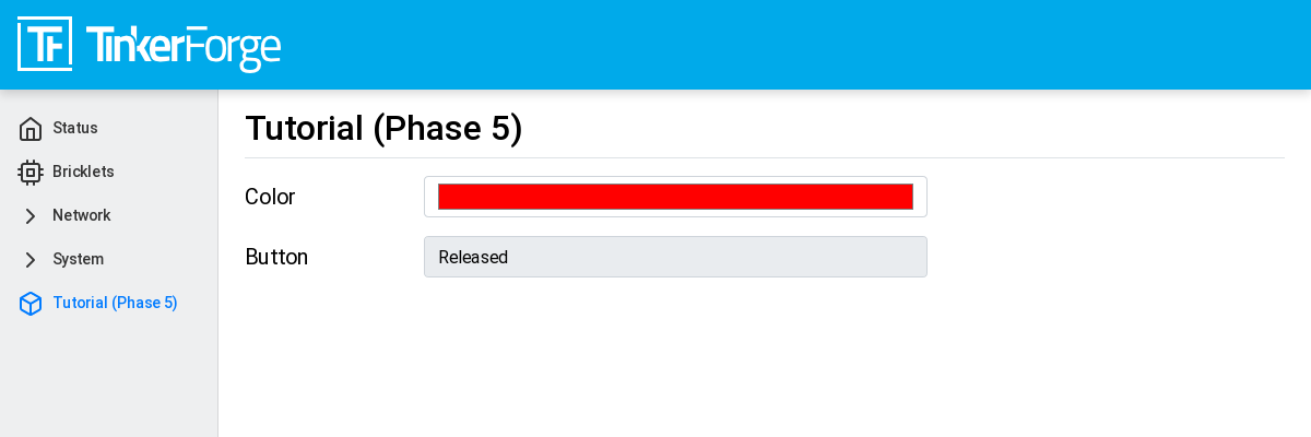
Phase 5: Communication Bricklet to Backend/Frontend
Module name for esp32.ini or esp32_ethernet.ini file is: Tutorial Phase 5
When this module is active a subwebsite with a color and button state view will show up named "Tutorial (Phase 5)":
Communicating the Button State
For that the file api.ts of the frontend module will be extended to receive
the state of the button. We do that by introducing a variable called
button. This can't be done by adding it to the existing config state
since this can be changed by the frontend module which should not be possible.
It should only be readable by the frontend module:
 export interface config
 {
     color: string
 }

 export interface state
 {
     button: boolean
 }
Therefore we introduce a new ConfigRoot object. Here the corresponding lines
of tutorial_phase_5.cpp:
 void TutorialPhase5::pre_setup()
 {
     config = Config::Object({
         {"color", Config::Str("#FF0000", 7, 7)}
     });

     config_update = config;

     state = Config::Object({
         {"button", Config::Bool(false)}
     });
 }
The new ConfigRoot object has to be also introduced to the API Manager.
For that the name tutorial_phase_5/state will be used, corresponding to the
changes in api.ts in the frontend module. Here the lines of tutorial_phase_5.cpp:
 void TutorialPhase5::register_urls()
 {
     api.addState("tutorial_phase_5/config", &config);

     api.addCommand("tutorial_phase_5/config_update", &config_update, {}, [this]() {
         String color = config_update.get("color")->asString();

         logger.printfln("Tutorial (Phase 5) module received color update: %s", color.c_str());
         config.get("color")->updateString(color);
         set_bricklet_color(color);
     }, false);

     api.addState("tutorial_phase_5/state", &state, {}, true);
 }
If the button is pressed we react to this event by introducing the function
button_state_changed_handler as a handler for the Button-State-Changed-Callback
of the RGB LED Button Bricklet. That means that this function is called if the button
is pressed or released and we can react to these events.
Here the corresponding lines of tutorial_phase_5.cpp:
 static void button_state_changed_handler(TF_RGBLEDButton *rgb_led_button, uint8_t state, void *user_data)
 {
     TutorialPhase5 *tutorial = (TutorialPhase5 *)user_data;
     tutorial->state.get("button")->updateBool(state == TF_RGB_LED_BUTTON_BUTTON_STATE_PRESSED);
 }

 void TutorialPhase5::setup()
 {
     if (tf_rgb_led_button_create(&rgb_led_button, nullptr, &hal) != TF_E_OK) {
         logger.printfln("No RGB LED Button Bricklet found, disabling Tutorial (Phase 5) module");
         return;
     }

     set_bricklet_color(config.get("color")->asString());

     tf_rgb_led_button_register_button_state_changed_callback(&rgb_led_button, button_state_changed_handler, this);
     uint8_t state;

     if (tf_rgb_led_button_get_button_state(&rgb_led_button, &state) != TF_E_OK) {
         logger.printfln("Could not get RGB LED Button Bricklet button state");
     } else {
         state.get("button")->updateBool(state == TF_RGB_LED_BUTTON_BUTTON_STATE_PRESSED);
     }

     logger.printfln("Tutorial (Phase 5) module initialized");

     initialized = true;
 }
In main.tsx any change of the tutorial_phase_5/state state will be handled
as the color changes are handled before:
util.addApiEventListener('tutorial_phase_5/state', () => {
    let state = API.get("tutorial_phase_5/state");

    this.setState({button: state.button});
});
A button press will be shown in the webinterface:

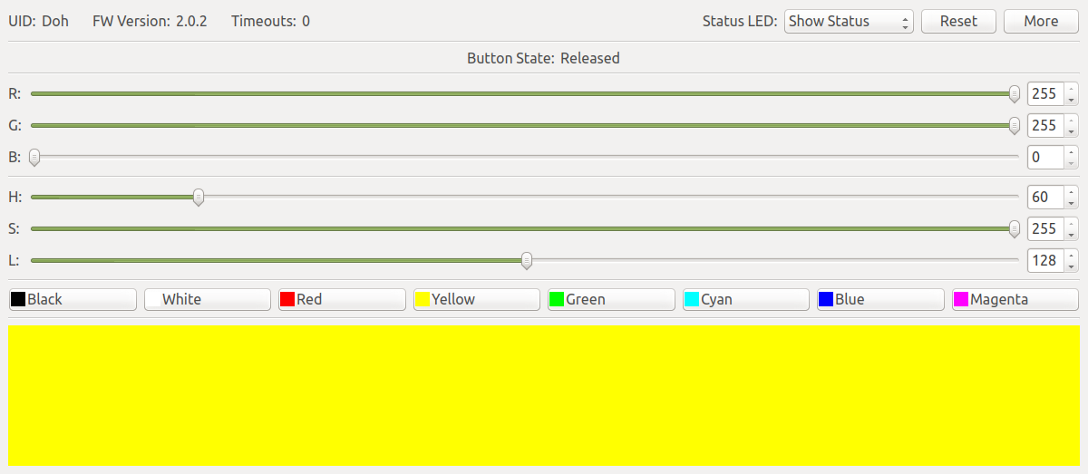
React to External Color Changes
With the standard firmware of the ESP32 Brick all Bricklets connected to the Brick
are externally accessible by the the API Bindings. These Bindings are also
used by the Brick Viewer. This feature is implemented by
the Proxy module. External color changes by the API Bindings are yet not handled
by our tutorial module, therefore external color changes will not be shown in the webinterface.
We will now fix that.
To handle external color changes by the tutorial module the color of the RGB LED Button
Bricklet will be requested all 1000 milliseconds and changes are transmitted by the
API manager to the webinterface. Here the corresponding lines of tutorial_phase_5.cpp:
 void TutorialPhase5::setup()
 {
     // ...

     uint8_t button_state;

     if (tf_rgb_led_button_get_button_state(&rgb_led_button, &button_state) != TF_E_OK) {
         logger.printfln("Could not get RGB LED Button Bricklet button state");
     } else {
         state.get("button")->updateBool(button_state == TF_RGB_LED_BUTTON_BUTTON_STATE_PRESSED);
     }

     task_scheduler.scheduleWithFixedDelay([this]() {
         poll_bricklet_color();
     }, 0, 1000);

     logger.printfln("Tutorial (Phase 5) module initialized");

     initialized = true;
 }

 void TutorialPhase5::poll_bricklet_color()
 {
     uint8_t red, green, blue;

     if (tf_rgb_led_button_get_color(&rgb_led_button, &red, &green, &blue) != TF_E_OK) {
         logger.printfln("Could not get RGB LED Button Bricklet color");
         return;
     }

     String color = "#" + num2hex(red) + num2hex(green) + num2hex(blue);
     config.get("color")->updateString(color);
 }
Color change from red to yellow in Brick Viewer:
Now the webinterface will show yellow:
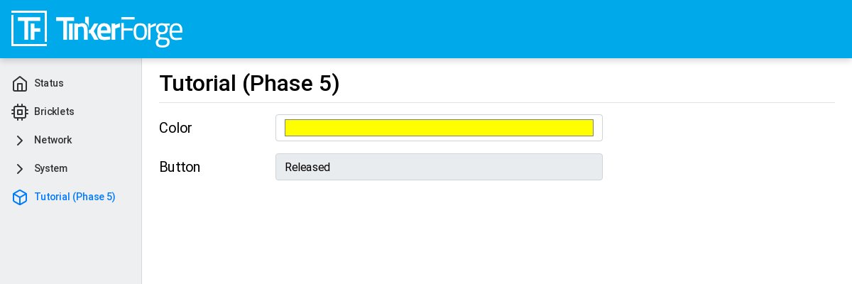
With that the whole communication path between hardware and webinterface is convered by this tutorial.