- Getting Started
- Hardware
- Bricks
- Bricklets
- Accelerometer Bricklet 2.0
- Air Quality Bricklet
- Ambient Light Bricklet 3.0
- Analog In Bricklet 3.0
- Analog Out Bricklet 3.0
- Barometer Bricklet
- Barometer Bricklet 2.0
- Breakout Bricklet
- CAN Bricklet
- CAN Bricklet 2.0
- CO2 Bricklet 2.0
- Color Bricklet
- Color Bricklet 2.0
- Compass Bricklet
- DC Bricklet 2.0
- Distance IR Bricklet
- Distance IR Bricklet 2.0
- Distance US Bricklet 2.0
- DMX Bricklet
- Dual Button Bricklet 2.0
- Dust Detector Bricklet
- E-Paper 296x128 Bricklet
- Energy Monitor Bricklet
- GPS Bricklet 2.0
- GPS Bricklet 3.0
- Hall Effect Bricklet
- Hall Effect Bricklet 2.0
- Humidity Bricklet 2.0
- IMU Bricklet 3.0
- Industrial Analog Out Bricklet 2.0
- Industrial Counter Bricklet
- Industrial Digital In 4 Bricklet 2.0
- Industrial Digital Out 4 Bricklet
- Industrial Digital Out 4 Bricklet 2.0
- Industrial Dual 0-20mA Bricklet
- Industrial Dual 0-20mA Bricklet 2.0
- Industrial Dual AC In Bricklet
- Industrial Dual AC Relay Bricklet
- Industrial Dual Analog In Bricklet 2.0
- Industrial Dual Relay Bricklet
- Industrial PTC Bricklet
- Industrial Quad Relay Bricklet 2.0
- IO-16 Bricklet
- IO-16 Bricklet 2.0
- IO-4 Bricklet 2.0
- Isolator Bricklet
- Joystick Bricklet
- Joystick Bricklet 2.0
- Laser Range Finder Bricklet 2.0
- LCD 128x64 Bricklet
- LCD 20x4 Bricklet
- LED Strip Bricklet 2.0
- Line Bricklet
- Linear Poti Bricklet
- Linear Poti Bricklet 2.0
- Load Cell Bricklet 2.0
- Motion Detector Bricklet 2.0
- Motorized Linear Poti Bricklet
- Multi Touch Bricklet
- Multi Touch Bricklet 2.0
- NFC Bricklet
- OLED 128x64 Bricklet 2.0
- OLED 64x48 Bricklet
- One Wire Bricklet
- Outdoor Weather Bricklet
- Particulate Matter Bricklet
- Performance DC Bricklet
- Piezo Speaker Bricklet
- Piezo Speaker Bricklet 2.0
- Real-Time Clock Bricklet
- Real-Time Clock Bricklet 2.0
- Remote Switch Bricklet 2.0
- RGB LED Bricklet 2.0
- RGB LED Button Bricklet
- Rotary Encoder Bricklet 2.0
- Rotary Poti Bricklet
- Rotary Poti Bricklet 2.0
- RS232 Bricklet
- RS232 Bricklet 2.0
- RS485 Bricklet
- Segment Display 4x7 Bricklet
- Segment Display 4x7 Bricklet 2.0
- Servo Bricklet 2.0
- Silent Stepper Bricklet 2.0
- Solid State Relay Bricklet 2.0
- Sound Intensity Bricklet
- Sound Pressure Level Bricklet
- Temperature Bricklet
- Temperature Bricklet 2.0
- Temperature IR Bricklet 2.0
- Thermal Imaging Bricklet
- Thermocouple Bricklet 2.0
- Tilt Bricklet
- UV Light Bricklet 2.0
- Voltage/Current Bricklet 2.0
- XMC1400 Breakout Bricklet
- Master Extensions
- Power Supplies
- Discontinued Products
- Timeline
- Software
- Kits
- Embedded Boards
- Specifications
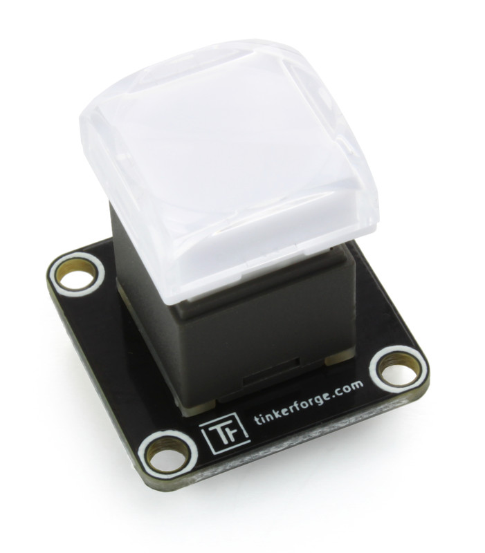
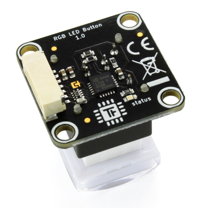
RGB LED Button Bricklet
Features
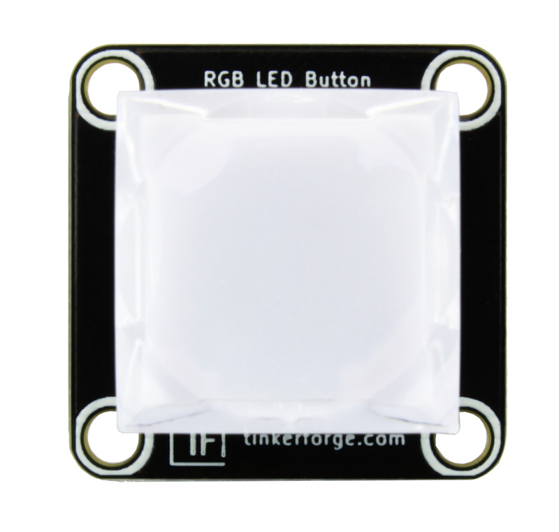
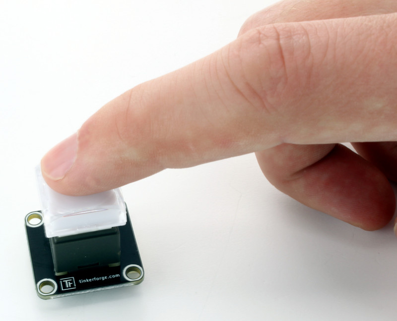
High quality 15mm x 15mm button
Adjustable RGB LED backlight
Replaceable/user-printable cap inlay
Description
The RGB LED Bricklet is equipped with an adjustable RGB backlit button. It can extend Bricks.
You can read the current state of the button (pressed/released) and adjust the color of the LED. The red, green and blue part of the LED can be controlled with 8 bit resolution each.
A white inlay is attached below the cap. This paper inlay can be replaced by a custom printed inlay (for example a power sign or an arrow or similar).
It is also possible to use events. This allows to react to button presses without polling.
Technical Specifications
Property |
Value |
|---|---|
Current Consumption (LEDs off) |
31mW (6.2mA at 5V) |
Current Consumption (LEDs on) |
207mW (41.4mA at 5V) |
LED Resolution |
8 bit per channel |
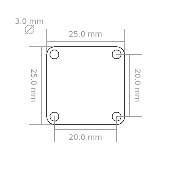
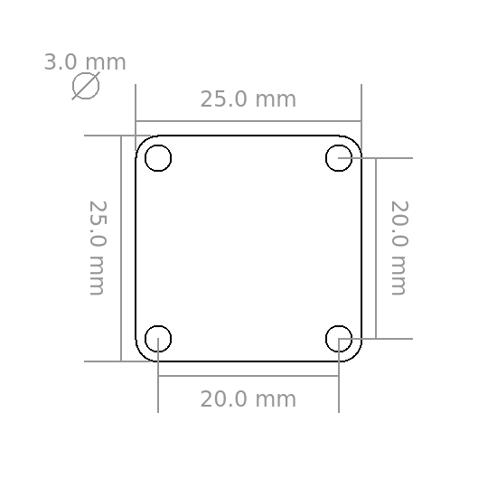
Inlay size |
14 x 14mm |
Button size |
15 x 15mm |
Cap size |
17.4 x 17.4mm |
Dimensions (W x D x H) |
25 x 25 x 30mm (0.98 x 0.98 x 1.18") |
Weight |
7g |
Resources
Button Inlay
The RGB LED Button Bricklet consists of four parts:
Bricklet with button and RGB LED,
White cap,
Inlay (optional, 14x14mm) and
Transparent cap.
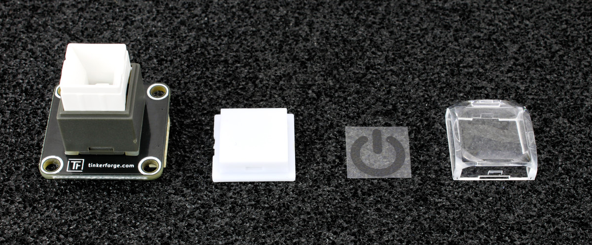
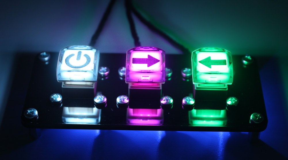
You can easily print your own inlays (size for perfect fit is 14x14mm). Put them between the white and the transparent cap.
For best results you can print the inlay on a transparent foil. A simple piece of white paper works too, but the LED brightness decreases a little bit.
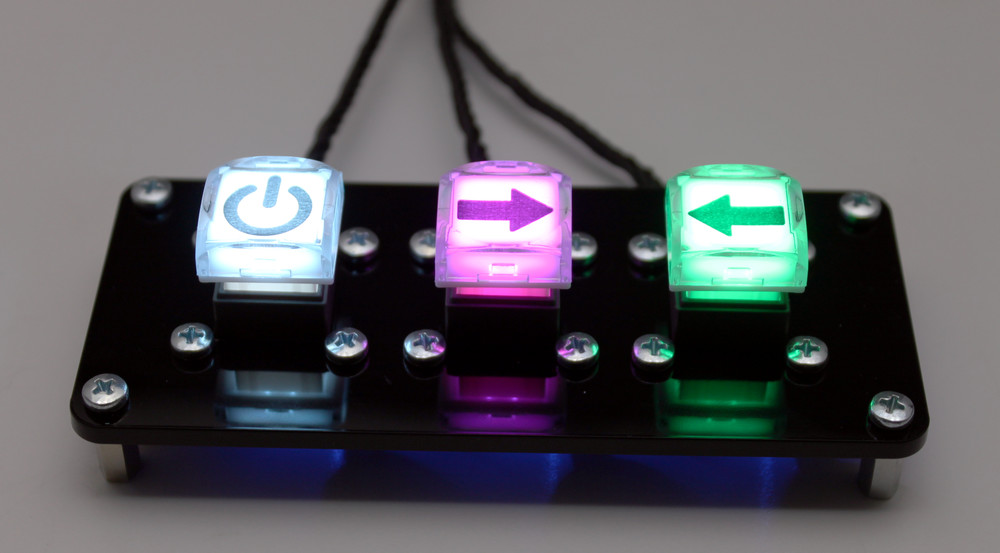
Below you can find an example of three RGB LED Button Bricklets with different inlays with and without ambient light. The symbol inlays were printed by a laser printer on transparent foil.
Test your RGB LED Button Bricklet
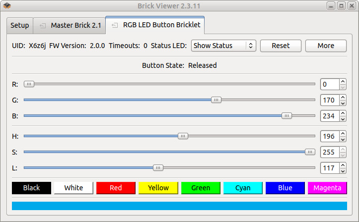
To test a RGB LED Button Bricklet you need to have Brick Daemon and Brick Viewer installed. Brick Daemon acts as a proxy between the USB interface of the Bricks and the API bindings. Brick Viewer connects to Brick Daemon. It helps to figure out basic information about the connected Bricks and Bricklets and allows to test them.
Connect the RGB LED Button Bricklet to a Brick with a Bricklet Cable.
If you connect the Brick to the PC over USB, you should see a new tab named "RGB LED Button Bricklet" in the Brick Viewer after a moment. Select this tab. You can now see button presses in the GUI and control the backlight RGB LED.
After this test you can go on with writing your own application. See the Programming Interface section for the API of the RGB LED Button Bricklet and examples in different programming languages.
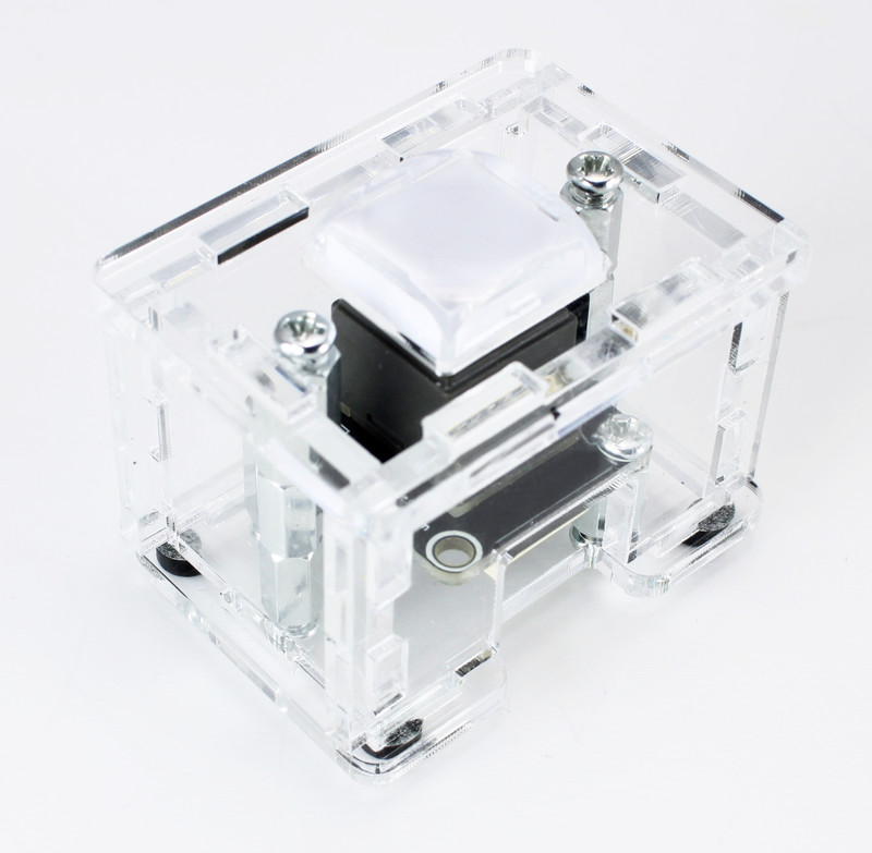
Case
A laser-cut case for the RGB LED Button Bricklet is available.
The assembly is easiest if you follow the following steps:
Screw 2x10mm spacers to bottom of Bricklet (use two diagonal wholes),
screw bottom plate to spacers,
screw 2x9mm and 1x10mm spacers to bottom plate,
build up side plates,
plug side plates into bottom plate and
screw top plate to top spacers.
Below you can see an exploded assembly drawing of the RGB LED Button Bricklet case:
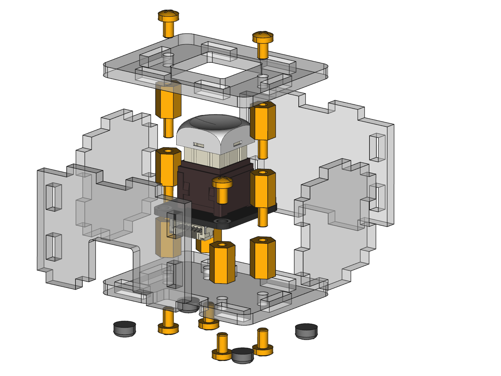
Hint: There is a protective film on both sides of the plates, you have to remove it before assembly.
Programming Interface
See Programming Interface for a detailed description.
Language |
API |
Examples |
Installation |
|---|---|---|---|
C/C++ |
|||
C/C++ for Microcontrollers |
|||
C# |
|||
Delphi/Lazarus |
|||
Go |
|||
Java |
|||
JavaScript |
|||
LabVIEW |
|||
Mathematica |
|||
MATLAB/Octave |
|||
MQTT |
|||
openHAB |
|||
Perl |
|||
PHP |
|||
Python |
|||
Ruby |
|||
Rust |
|||
Shell |
|||
Visual Basic .NET |
|||
TCP/IP |
|||
Modbus |