IMU Brick
Note
The IMU Brick is discontinued and is no longer sold. The IMU Brick 2.0 is the recommended replacement.
Features
Full fledged IMU/AHRS with 9 degrees of freedom (3-axis each: accelerometer, compass, gyroscope)
No accumulating errors, no gimbal lock!
Factory calibrated, easy to recalibrate
Calculates quaternions as well as roll, pitch and yaw
Directly readable by USB, extendable by two Bricklet ports
Description
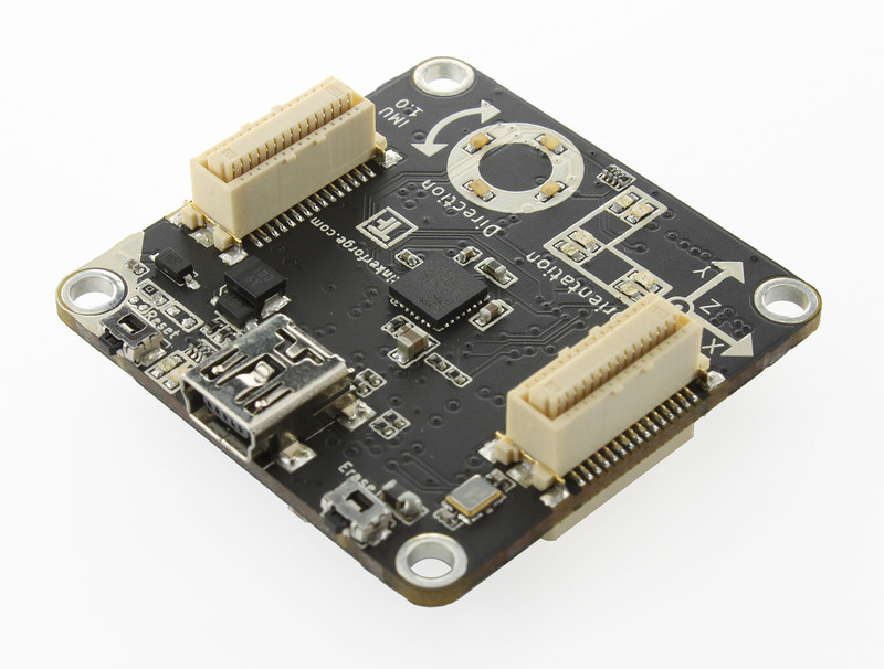
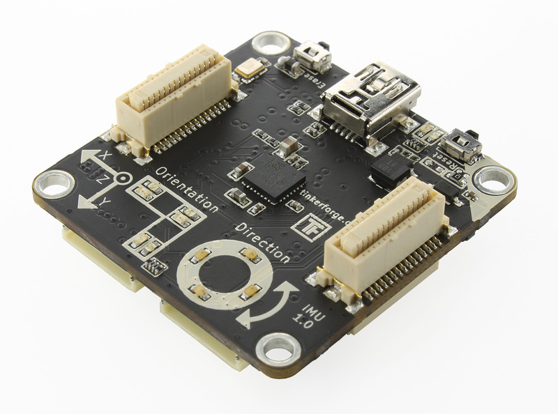
The IMU Brick is equipped with a 3-axis accelerometer, magnetometer (compass) and gyroscope and works as a USB inertial measurement unit. It can measure 9 degrees of freedom and computes quaternions as well as roll, pitch and yaw information. It is a complete attitude and heading reference system.
The API, provided for many programming languages, allows access to the calculated data and also the acceleration, magnetic field and angular velocity of the three axes. If the quaternion representation is used, the IMU Brick does not have a gimbal lock, as known from Euler angles.
Two Bricklet ports can be used to extend the features of this Brick. For Example a GPS Bricklet can be attached to get position information. A Youtube video shows, how the Brick can be used together with a Barometer Bricklet to gain altitude information.
The IMU Brick can be use together with other Bricks in a stack. For example an additional Master Brick with Master Extension allows to replace the USB connection by other cable based (RS485, Ethernet) or wireless (WIFI) connections.
Technical Specifications
Property |
Value |
|---|---|
Acceleration, Magnetic, Angular Velocity Resolution |
12bit, 16bit, 16bit |
Roll, Pitch, Yaw Resolution |
0.01° steps |
Quaternion Resolution |
32bit |
Sampling Rate |
500Hz |
Bricklet Ports |
2 |
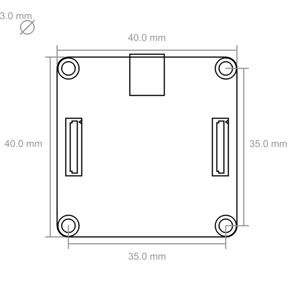
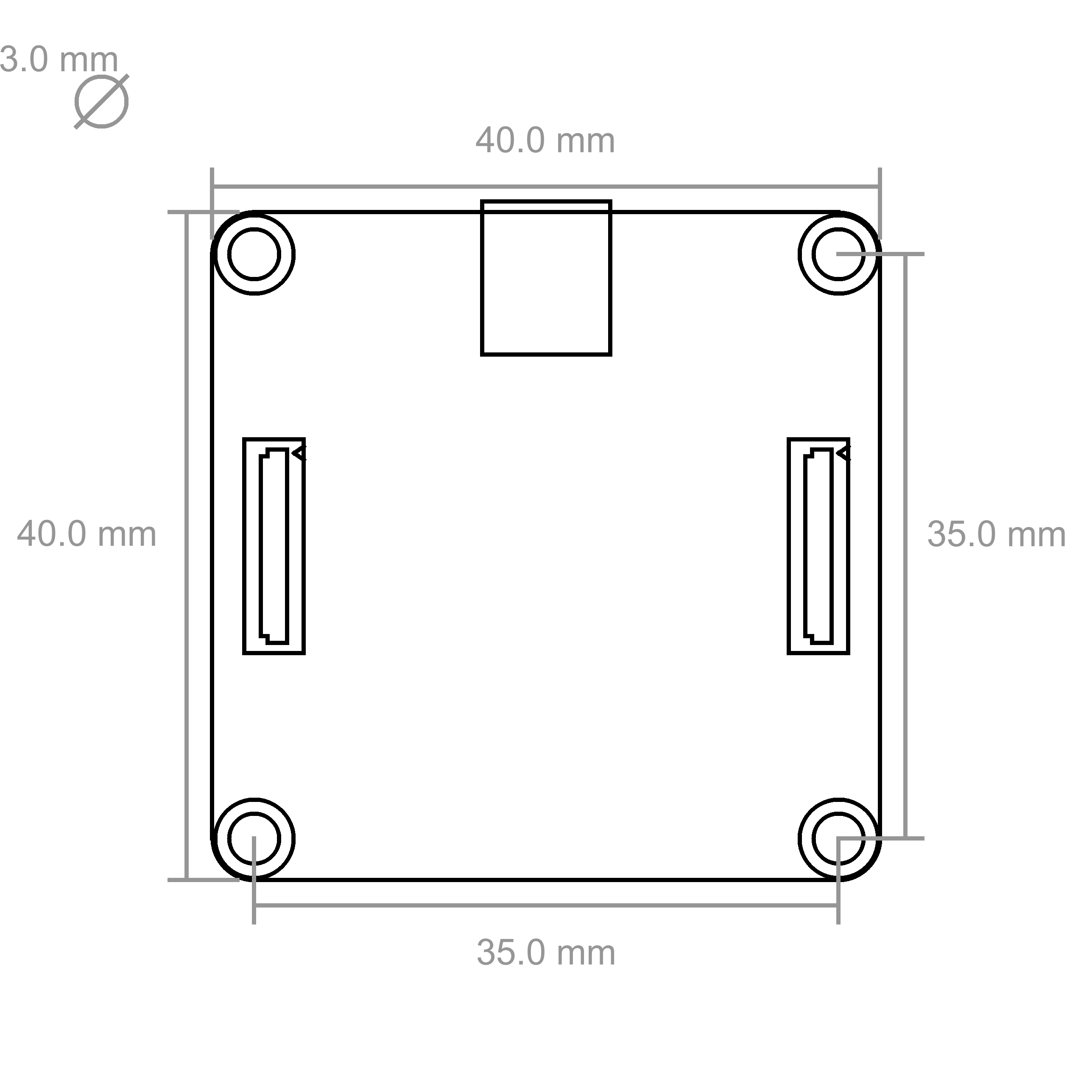
Dimensions (W x D x H) |
40 x 40 x 16mm (1.57 x 1.57 x 0.63") |
Weight |
12g |
Current Consumption |
300mW (60mA at 5V) |
Resources
Connectivity
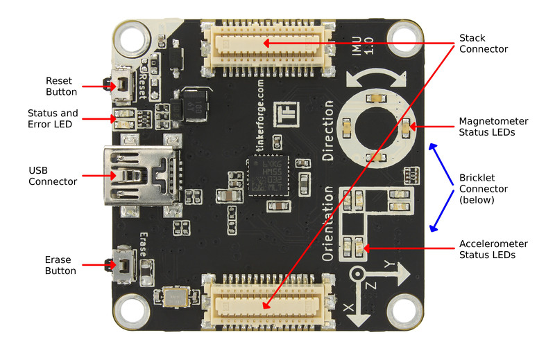
The following picture depicts the different connection possibilities of the IMU Brick.
Test your IMU Brick
To test a IMU Brick you need to have Brick Daemon and Brick Viewer installed. Brick Daemon acts as a proxy between the USB interface of the Bricks and the API bindings. Brick Viewer connects to Brick Daemon. It helps to figure out basic information about the connected Bricks and Bricklets and allows to test them.
Now connect the Brick to the PC over USB, you should see a new tab named "IMU Brick" in the Brick Viewer after a moment. Select this tab.
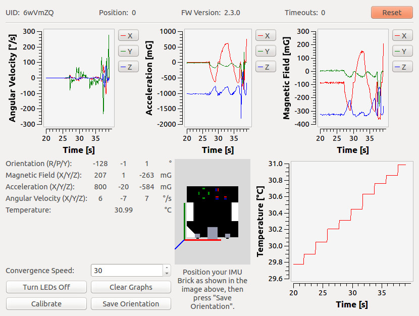
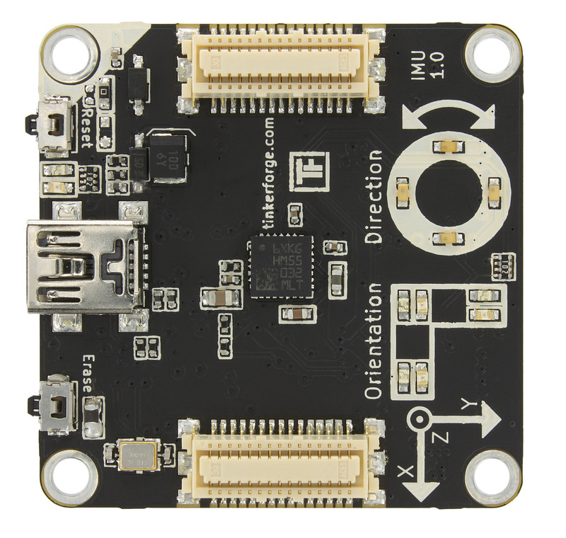
You can see all of the available data form the IMU Brick. If you hold the IMU Brick in the orientation as shown in the image and press "Save Orientation", the movements that you make with the IMU Brick should be mirrored in the Brick Viewer. Before you press "Save Orientation" you should hold the IMU Brick still for about 15 seconds, so it can converge to the correct position.
After this test you can go on with writing your own application. See the Programming Interface section for the API of the IMU Brick and examples in different programming languages.
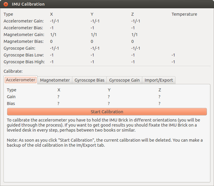
Calibration
The IMU Brick comes factory calibrated and should work out of the box. It is however easy to recalibrate, if necessary.
The factory calibration has taken place in a room without any significant interfering magnetic fields. If you want to operate the IMU Brick near something that has a magnetic field (e.g. near a motor), you will have to recalibrate the magnetometer in the exact position where it will be used later on!
To calibrate the magnetometer click on "Calibrate" in the Brick Viewer and choose the "Magnetometer" tab of the new window. Press "Start Calibration" and now change the orientation of the IMU Brick until the bias and gain values shown in the GUI do not change anymore. Press "Ready" when this is the case and you are done.
Accelerometer and gyroscope can be calibrated similarly, follow the instructions as given by the calibration tool. We recommend that you export the calibration before you start recalibrating the accelerometer and the gyroscope, so you are able to go back to the old calibration.
We recommend that you don't try to recalibrate the gyroscope gain, it is not possible without suitable external machinery.
The factory calibration for your IMU Brick can be found at:
https://download.tinkerforge.com/imu_calibration/YOUR_IMU_UID.txt
Replace YOUR_IMU_UID by the UID of your IMU Brick.
If you accidentally miscalibrated a sensor or you
flashed a new firmware version, you can reimport the factory calibration.
To do so go to the "IMU Brick" in the Brick Viewer, click the "Calibrate"
button and select the "Im/Export" tab. Finally copy and paste the content of
YOUR_IMU_UID.txt to the textbox and click "Import".
Since Brick Viewer version 1.1.13 you can also click the "Restore Factory Calibration" button, that automatically downloads and imports the factory calibration for you.
A video how we calibrate the IMU Bricks can be found: here.
Quaternions vs Euler Angles
We highly recommend that you use quaternions in your project rather than Euler angles (yaw, pitch and roll), since the latter exhibits a gimbal lock.
A formula to transform quaternions to rotation matrices can be found in the API documentation. Note that Euler angles always have an order in which they are applied. The order for the IMU Brick is: roll, yaw, pitch.
Computation of independent Angles
It is not possible to get angles for all 3 axis that are completely independent. At least at the gimbal lock positions there will be jumps of 180° for some of the angles. This is simply not possible otherwise.
Note
All of this only applies to old IMU Brick. The new IMU Brick 2.0 directly reports its orientation in independent Euler angles.
If you want rotation angles for the x, y and z axis for a given base position, you have to rotate the quaternion according to your base position and calculate the angles after that. The following Python example does exactly that and it should be easy to understand and translate in other languages. Note that there are gimbal locks at +90° and -90° from each of the angles. The base position will be (0,0,0):
#!/usr/bin/env python
# -*- coding: utf-8 -*-

from tinkerforge.ip_connection import IPConnection
from tinkerforge.brick_imu import IMU

import math
import time

class Q:
    HOST = "localhost"
    PORT = 4223
    UID = "XXYYZZ" # Change XXYYZZ to the UID of your IMU Brick

    def __init__(self):
        self.base_x = 0.0
        self.base_y = 0.0
        self.base_z = 0.0
        self.base_w = 0.0

        self.ipcon = IPConnection() # Create IPconnection
        self.imu = IMU(self.UID, self.ipcon) # Create device object
        self.ipcon.connect(self.HOST, self.PORT) # Connect to brickd

        # Wait for IMU to settle
        print 'Set IMU to base position and wait for 10 seconds'
        print 'Base position will be 0 for all angles'
        time.sleep(10)
        q = self.imu.get_quaternion()
        self.set_base_coordinates(q.x, q.y, q.z, q.w)

        # Set period for quaternion callback to 10ms
        self.imu.set_quaternion_period(10)

        # Register quaternion callback
        self.imu.register_callback(self.imu.CALLBACK_QUATERNION, self.quaternion_cb)

    def quaternion_cb(self, x, y, z, w):
        # Use conjugate of quaternion to rotate coordinates according to base system
        x, y, z, w = self.make_relative_coordinates(-x, -y, -z, w)

        x_angle = int(math.atan2( 2.0*(y*z - w*x), 1.0 - 2.0*(x*x + y*y))*180/math.pi)
        y_angle = int(math.atan2(-2.0*(x*z + w*y), 1.0 - 2.0*(x*x + y*y))*180/math.pi)
        z_angle = int(math.atan2(-2.0*(x*y + w*z), 1.0 - 2.0*(x*x + z*z))*180/math.pi)

        print 'x: {0}, y: {1}, z: {2}'.format(x_angle, y_angle, z_angle)

    def set_base_coordinates(self, x, y, z, w):
        self.base_x = x
        self.base_y = y
        self.base_z = z
        self.base_w = w

    def make_relative_coordinates(self, x, y, z, w):
        # Multiply base quaternion with current quaternion
        return (
            w * self.base_x + x * self.base_w + y * self.base_z - z * self.base_y,
            w * self.base_y - x * self.base_z + y * self.base_w + z * self.base_x,
            w * self.base_z + x * self.base_y - y * self.base_x + z * self.base_w,
            w * self.base_w - x * self.base_x - y * self.base_y - z * self.base_z
        )

if __name__ == "__main__":
    q = Q()

    raw_input('Press key to exit\n') # Use input() in Python 3
    q.ipcon.disconnect()
Paul Balzer from MechLab Engineering has additional code on GitHub that uses the quaternions to calculate yaw, pitch and roll in a vehicle coordinate system according to DIN70000. It is notably consistently a right-handed coordinate system.
How it works
With the sensor data gathered by the IMU Brick (angular velocity, acceleration and magnetic field), it is possible to apply sensor fusion to acquire an absolute orientation.
For this process often a Kalman Filter is used. The filter that is used in the IMU Brick is based on this paper by S. O. Madgwick. In our tests this new state of the art filter could achieve significantly better results than a Kalman Filter. Madgwick describes the approach of his filter as follows:
[...] the filter calculates the orientation by numerically integrating the estimated orientation rate. It is computed as the rate of change of orientation measured by the gyroscopes. The magnitude of the gyroscope measurement error is removed in the direction of the estimated error, which is computed from accelerometer and magnetometer measurements.
The following image shows the different steps of the filter:
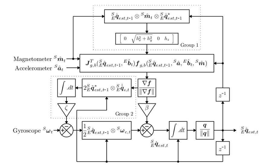
Image and explanation from S. O. Madgwick: "An efficient orientation filter for inertial and inertial/magnetic sensor arrays", University of Bristol, April 2010.
Programming Interface
See Programming Interface for a detailed description.
Language |
API |
Examples |
Installation |
|---|---|---|---|
C/C++ |
|||
C# |
|||
Delphi/Lazarus |
|||
Go |
|||
Java |
|||
JavaScript |
|||
LabVIEW |
|||
Mathematica |
|||
MATLAB/Octave |
|||
MQTT |
|||
openHAB |
|||
Perl |
|||
PHP |
|||
Python |
|||
Ruby |
|||
Rust |
|||
Shell |
|||
Visual Basic .NET |
|||
TCP/IP |
|||
Modbus |