- Getting Started
- Hardware
- Bricks
- Bricklets
- Master Extensions
- Power Supplies
- Discontinued Products
- Bricks
- Bricklets
- Accelerometer Bricklet
- Ambient Light Bricklet
- Ambient Light Bricklet 2.0
- Analog In Bricklet
- Analog In Bricklet 2.0
- Analog Out Bricklet
- Analog Out Bricklet 2.0
- CO2 Bricklet
- Current12 Bricklet
- Current25 Bricklet
- Distance US Bricklet
- Dual Button Bricklet
- Dual Relay Bricklet
- GPS Bricklet
- Humidity Bricklet
- Industrial Analog Out Bricklet
- Industrial Digital In 4 Bricklet
- Industrial Dual Analog In Bricklet
- Industrial Quad Relay Bricklet
- IO-4 Bricklet
- Laser Range Finder Bricklet
- LCD 16x2 Bricklet
- LED Strip Bricklet
- Load Cell Bricklet
- Moisture Bricklet
- Motion Detector Bricklet
- NFC/RFID Bricklet
- OLED 128x64 Bricklet
- Piezo Buzzer Bricklet
- PTC Bricklet
- PTC Bricklet 2.0
- Remote Switch Bricklet
- RGB LED Bricklet
- RGB LED Matrix Bricklet
- Rotary Encoder Bricklet
- Solid State Relay Bricklet
- Temperature IR Bricklet
- Thermocouple Bricklet
- UV Light Bricklet
- Voltage Bricklet
- Voltage/Current Bricklet
- Master Extensions
- Timeline
- Software
- Kits
- Embedded Boards
- Specifications
Dual Relay Bricklet

Note
The Dual Relay Bricklet is discontinued and is no longer sold. The Industrial Dual Relay Bricklet is the recommended replacement.
Features
Two relays to switch AC/DC devices
Switches up to 240VAC/10A and 30VDC/7A
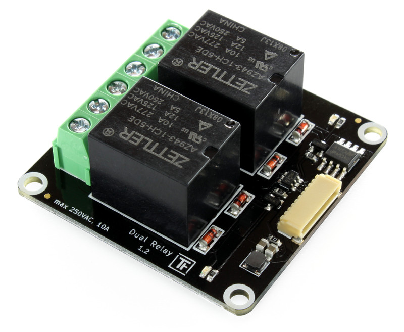
Description
The Dual Relay Bricklet can be used to extend the features of Bricks by two relays. Each relay has three terminals such that the terminal in the middle is electrically connected to the terminal left or right depending on the state. The state is visualized by a LED. The new hardware version 1.2 is equipped with extensive protection circuitry against interference of inductive load switching.
You can use this Bricklet to switch power supplies, motors, lamps, etc. Consider the maximum voltage and current.
If you want to switch inductive loads, please see: Inductive Load Switching.
Warning
Terminals and contacts are not insulated. If you want to switch higher voltages, consider to put the Dual Relay Bricklet in a casing. Touching the contacts is potentially life-threatening!
Technical Specifications
Property |
Value |
|---|---|
Relay |
AZ943-1CH-5DE |
Current Consumption |
75mA (per Relay) |
Maximum Voltage/Current |
AC: 240V/10A
DC: 30V/7A
|
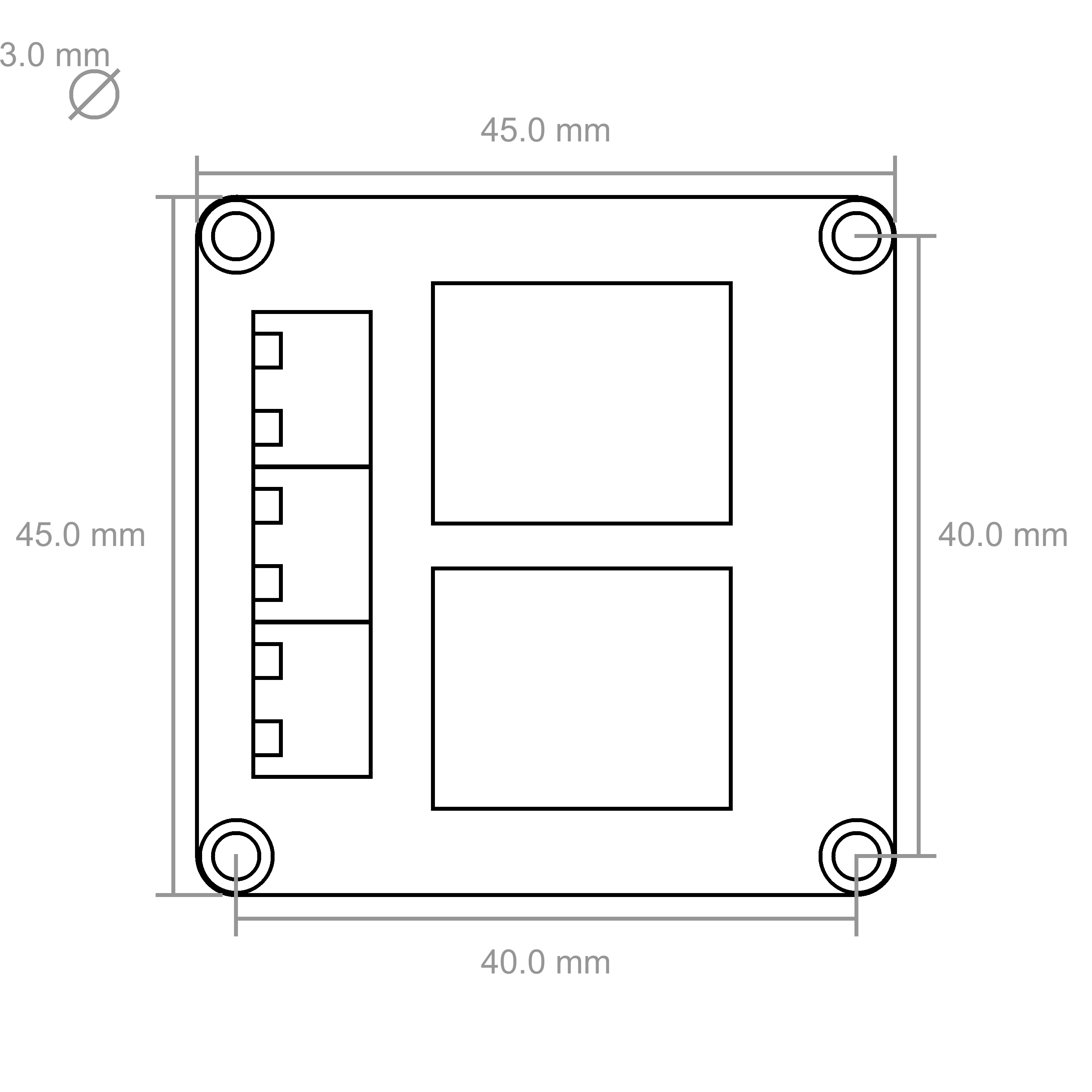
Dimensions (W x D x H) |
45 x 45 x 25mm (1.77 x 1.77 x 0.98") |
Weight |
29g |
Resources
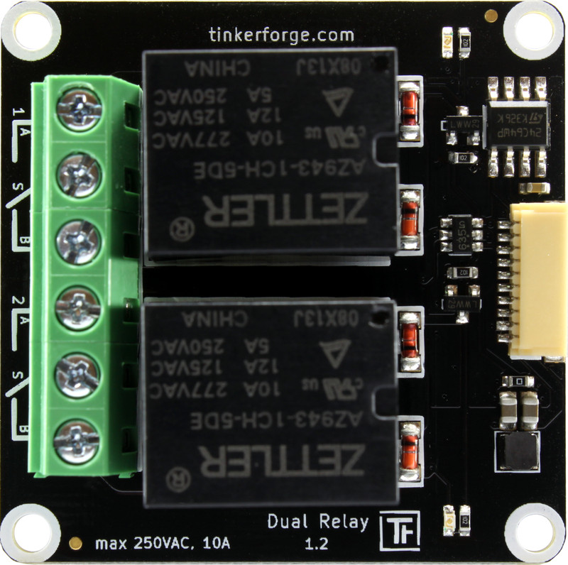
Connectivity
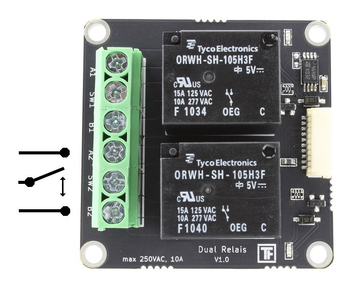
Each relay has three connectors: A, SW and B. SW is connected to A or B depending on the switching state of the relay.
If the relay is switched off, then SW is connected to B
If the relay is switched on, then SW is connected to A
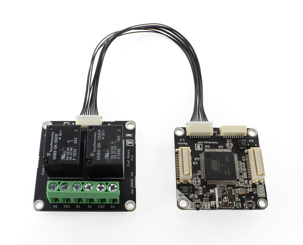
Test your Dual Relay Bricklet
To test a Dual Relay Bricklet you need to have Brick Daemon and Brick Viewer installed. Brick Daemon acts as a proxy between the USB interface of the Bricks and the API bindings. Brick Viewer connects to Brick Daemon. It helps to figure out basic information about the connected Bricks and Bricklets and allows to test them.
Connect the Dual Relay Bricklet to a Brick with a Bricklet Cable (see picture below).
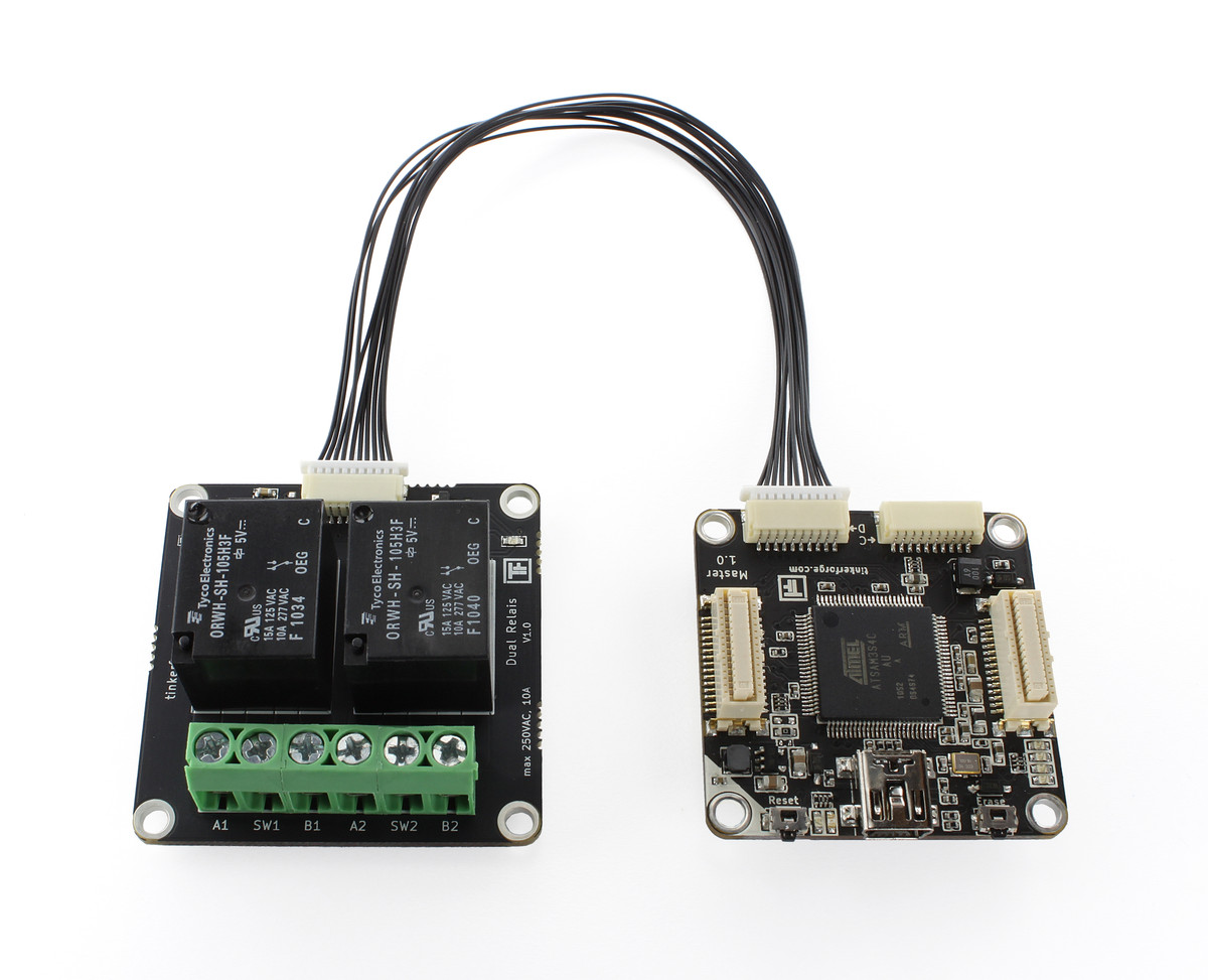
If you connect the Brick to the PC over USB, you should see a new tab named "Dual Relay Bricklet" in the Brick Viewer after a moment. Select this tab. If everything went as expected the Brick Viewer should look as depicted below.
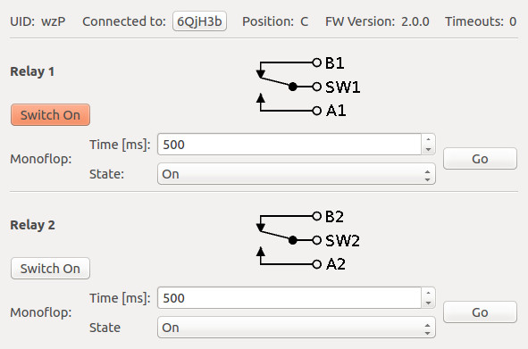
Play around with the two relay buttons, you should hear the relay switching when toggling the buttons. An LED indicates the current state of each relay.
After this test you can go on with writing your own application. See the Programming Interface section for the API of the Dual Relay Bricklet and examples in different programming languages.
Inductive Load Switching
Without external components the switching of inductive loads can cause interference in the system that can lead to malfunctions or destroyed components. Typical examples for inductive loads are motors and solenoids, but these problems can also occur when switching e.g. fluorescent lamps.
If you want to switch an inductive load you need external components, e.g. a varistor or a combination of a resistor and a capacitor parallel to the load.
More information about protection circuitries can be found here.
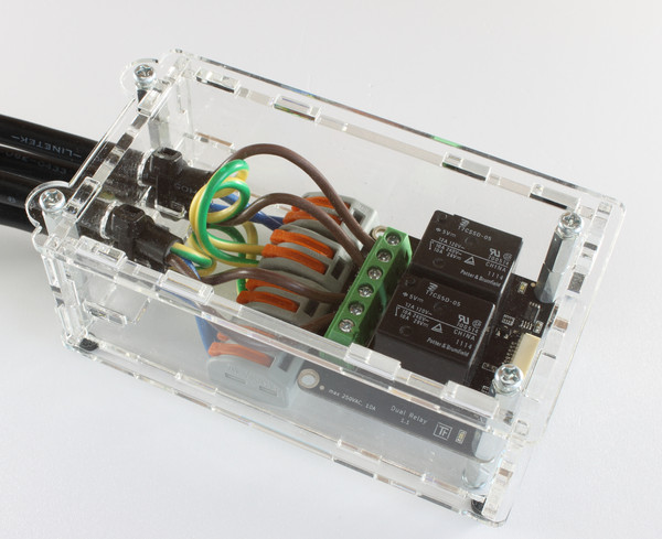
Case
A laser-cut case for the Dual Relay Bricklet is available.
The case of the Dual Relay Bricklet is delivered including cable ties for a cable relief and WAGO connecting clamps to join wires. The case is big enough to accommodate the cable relief as well as the WAGO clamps.
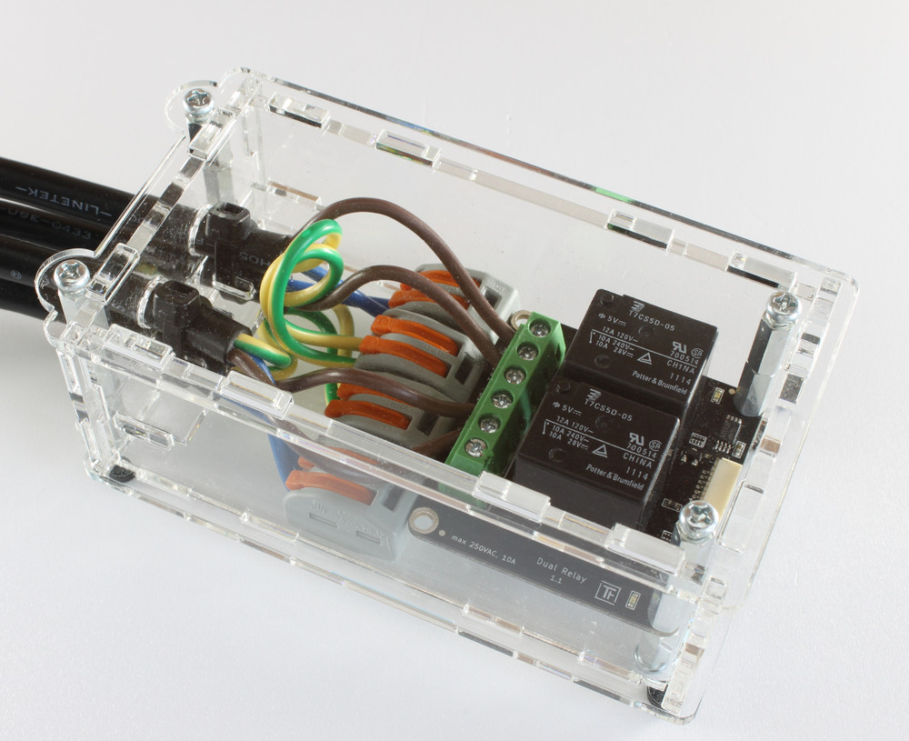
The internal construction can look as follows (with one as well as two relays connected)
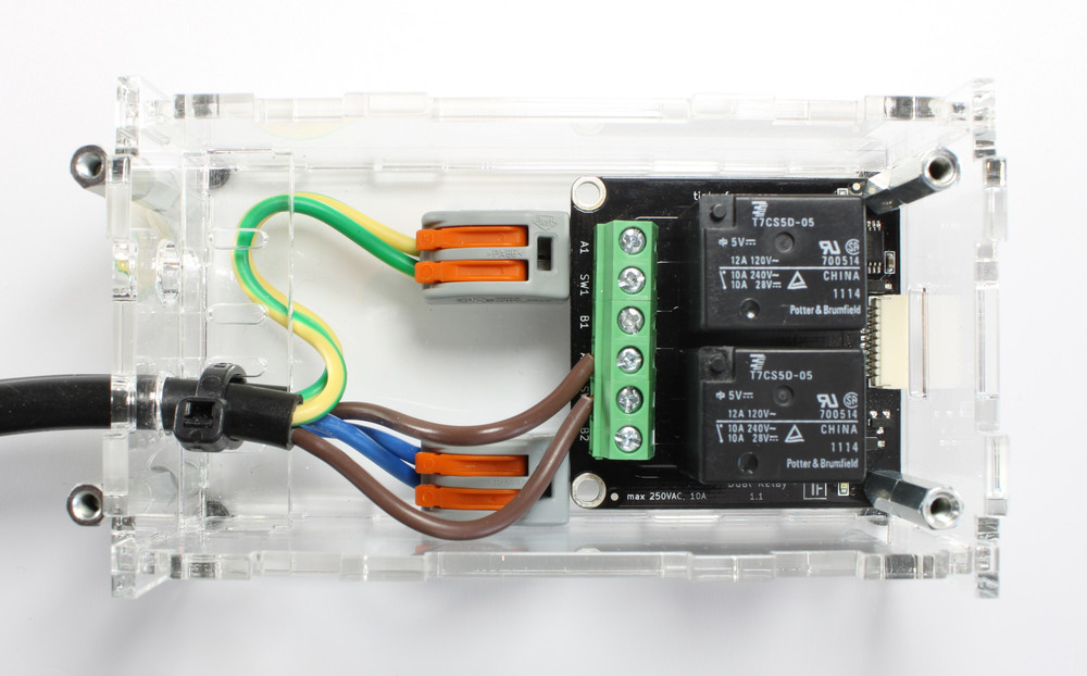
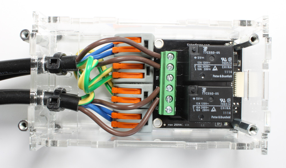
The protective conductor (brown) is switched with the Dual Relay Bricklet. The external conductor (green-yellow) and the neutral conductor (blue) are coupled with the WAGO connecting clamps.
It is important that the external conductor is longer then the other cables. This way it is assured that the external conductor will be pulled of at last if the cable relief is overstrained or defect. We recommend the following length for the cables and the stripping:
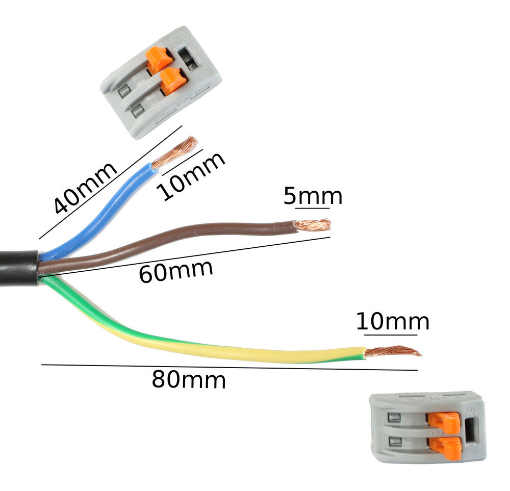
The assembly is easiest if you follow the following steps:
screw spacers to Bricklet
screw Bricklet to bottom plate with spacers
build up side plates (including cable relief)
plug side plates into bottom plate
add cabling and WAGO clamps
tie cable ties to cables
screw top plate to top spacers
Warning
Never work inside the case when components are carrying voltage!
The exact position of each part can be seen in the following exploded assembly drawing of the Dual Relay Bricklet case:
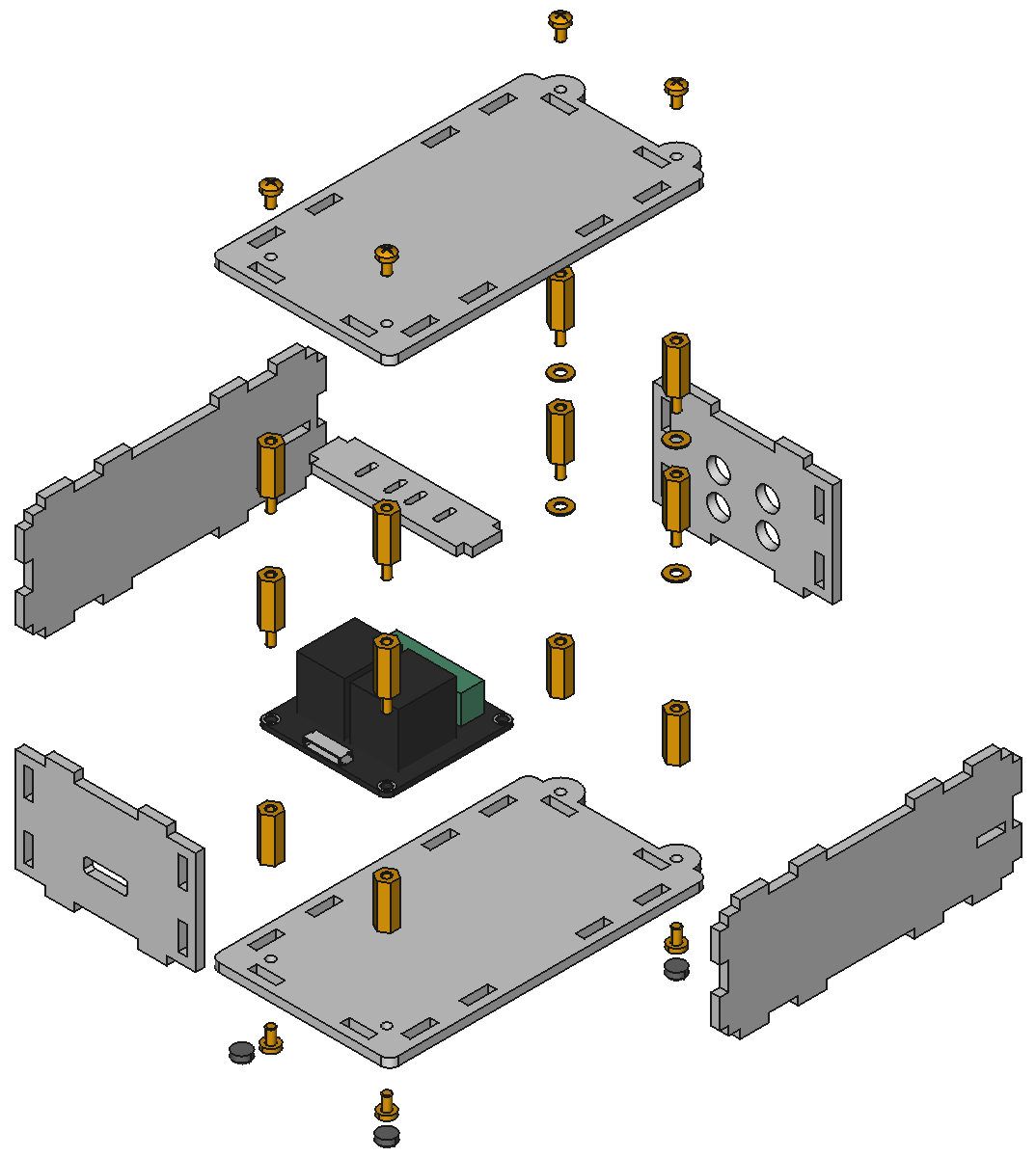
Hint: There is a protective film on both sides of the plates, you have to remove it before assembly.
Programming Interface
See Programming Interface for a detailed description.
Language |
API |
Examples |
Installation |
|---|---|---|---|
C/C++ |
|||
C# |
|||
Delphi/Lazarus |
|||
Go |
|||
Java |
|||
JavaScript |
|||
LabVIEW |
|||
Mathematica |
|||
MATLAB/Octave |
|||
MQTT |
|||
openHAB |
|||
Perl |
|||
PHP |
|||
Python |
|||
Ruby |
|||
Rust |
|||
Shell |
|||
Visual Basic .NET |
|||
TCP/IP |
|||
Modbus |