Today we want to write about the long story of development of the Silent Stepper Brick. Our current Stepper Brick generates, like most stepper drivers, audible high-pitched noises when a motor is driven. The reason for these noises lays in the motor inductance together with the current control. In full step mode the noise is usually louder then if the motor is driven in micro-step mode (1/4, 1/8, …). Since there are applications in which this audible high-pitched noise is undesirable, we decided to work on a quieter alternative. The Silent Stepper Brick
Development part 1
The size of the Silent Stepper Brick is pre-determined as 4x4cm. If you exclude the space for the board-to-board connectors, the Bricklet connectors and the microcontroller, it is clear that we can only use an integrated driver solution. The TMC2100 is a integrated driver IC that supports different kinds of current control and a silent mode (Stealth Chop). The driver supports a maximum phase current of 1.2A and up to 256 micro steps. Thus stepper motors can be spun precisely and the maximum current fits to the stepper motors that we have in our shop.
We started the development of a first prototype with a TMC2100 driver IC. We found out that the prototype had problems with high motor speeds: The torque would suddenly collapse and the motor could stop abruptly. After a long search we found two reasons for this:
-
Our layout of the prototype wasn’t optimal, so we had to develop a new one.
-
Stepper motors have a resonance frequency. If the motor spins at the right frequency it can become unstable. Usually it is easiest to just accelerate quickly trough this frequency. Since we had the additional problems with the layout, we first didn’t realize that we just found a normal behavior and there was no other design error.
After we overcame these problems and were nearly done with the development, there was a price adjustment: Beside the TMC2100 there is also the TMC2130. This driver has many more settings to play around with and additional exciting features. When we started the development the TMC2130 was significantly more expensive then the 2100, so we decided to use the simpler TMC2100. Now suddenly both drivers had nearly the same price, thus we decided to use the TMC2130. We had basically had to start with the development from scratch…
The TMC2100 has a simple interface. It is configurable over a few pins, which results in few settings. The TMC2130 on the other hand has a SPI interface and quite a number of different adjustment possibilities. We had to start the software from scratch and learn about all of the different settings. Since we already had a Stepper Brick the new Silent Stepper Brick did not have the highest priority, so this whole back and force did take a lot of time. The TMC2130 does have a internal clock that is used for the current control etc. The internal clock is however quite inaccurate and the accuracy is highly temperature dependent. In tests we found that the behavior of the driver changed slightly with changing temperatures, which we found unacceptable. We could of course easily provide a precise clock signal with our main processor, but we had to make yet another prototype for this!
EMC Laboratory
During the development of our products we routinely check for electromagnetic compliance. Since the design and the software has a big influence on this, we can only do the tests at the end of the development phase. Clock signals, high frequency buses etc have big influence.
We often visit a professional EMC Laboratory, but since these measurements can be quite expensive as well as time intensive, we now set up our own small EMC pre-compliance testing laboratory.
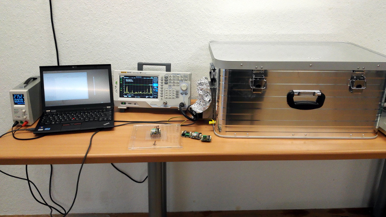
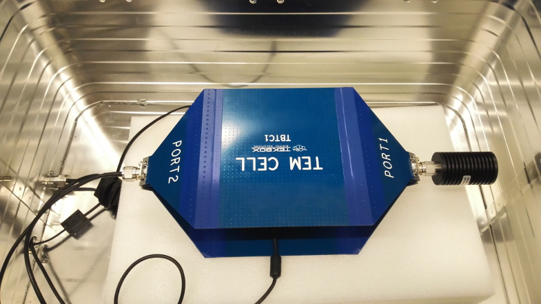
We use a Rigol DSA815 spectrum analyzer, a TEM cell and a big metal case to shield the device under test. With this set up we can’t guarantee the same measurement precision as a real EMC laboratory. However, we can usually still find out if a device exceeds the regulatory radiation limits. This way we can find EMC problems oftentimes before we do the real tests in a EMC laboratory.
A spectrum analyzer shows the amplitude for a specified band of frequencies, i.e. the strength of the electromagnetic radiation for individual frequencies. Without any shielding you will measure radio stations, gsm networks etc additionally to your device under test. Thus it is important that we try to shield the whole device during the testing as best as possible.
If a trace on the circuit board carries a signal with a specific frequency, you may find multiples of this frequency with the spectrum analyzer. The following photo shows the multiples of the Frequency 12.8 MHz.
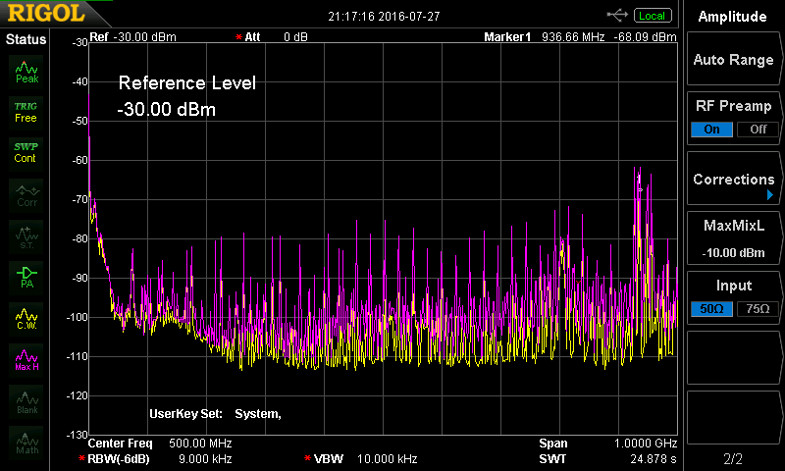
If you don’t immediately now which part of the circuit might create this frequency, you can use so called near-field probes. These can be used to measure the radiation locally, even down to a single trace or a single pin of a IC.
The interference can have different reasons. It can be a bad layout, steep signal edges, problems with grounding etc. Sometimes it is possible to reduce the radiation with a simple change of a part value (for example a different resistance for a series resistor in a signal path). Often there is no easy fix and the layout has to be revised.
Development part 2
Unfortunately we didn’t write about our measurements of electromagnetic interference without reason. We finished the development of the Silent Stepper Brick in time to be able to produce them this year. As a last step we wanted to do some EMC measurements. We used our own small laboratory for a first test and the measurement results were underwhelming to say the least.
We could easily see the multiples of the clock signal that we connected from the processor to the TMC2130 (see image above). The peaks seem to be barely below the limit, but the risk to go to the EMC laboratory with the board was just too high.
We did already have a series resistor in the trace of the clock line to be able to control the slew rate (edge steepness) of the signal. Unfortunately we were not able to find any resistor value that would significantly decrease the radiation problems. Thus we had to order another prototype. Each prototype will cost about two weeks of time with an additional 1/2 - 1 day time investment to actually build the prototype (including finding and removing solder errors etc).
With the new prototype we wanted to be on the safe side, so we ordered two variants: one with a better clock signal routing and more filter possibilities and one with a completely modified ground layer layout. During the tests of the new prototypes we found out that the new ground layer idea did not help (in fact the results were worse). Fortunately the additional filtering on the other prototype did the trick! We could now be very sure that we would satisfy the regulatory electromagnetic radiation limits.
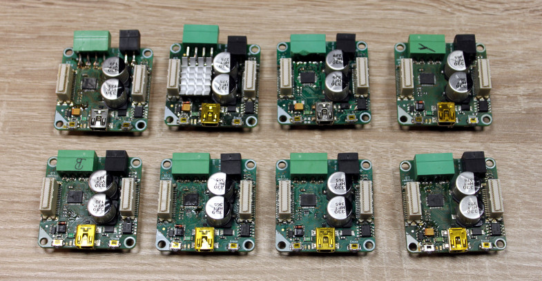
In sum we made 8 prototypes during the development process of the Silent Stepper Brick:
What now?
The circuit boards will be ordered next week. Because of Christmas and New Year the delivery will take longer then normal, but we are pretty sure that you will be able to buy Silent Stepper Bricks in the beginning of march. You can look forward for a nice comparison video of the new and old Stepper Brick.