Blog

RED Brick: Does it work?

RED Brick prototype

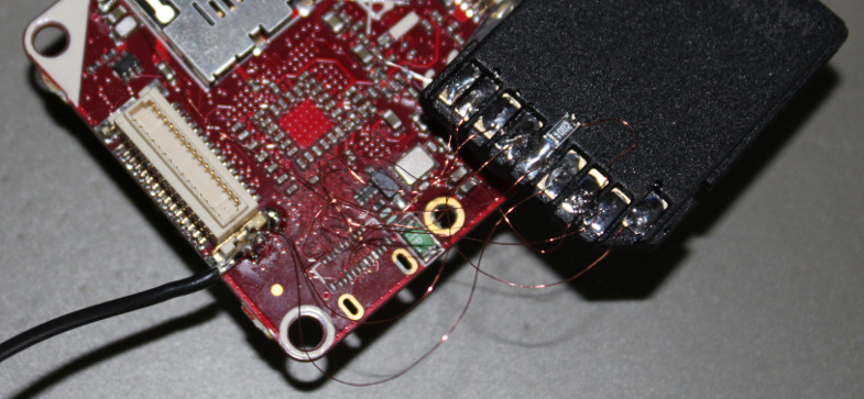
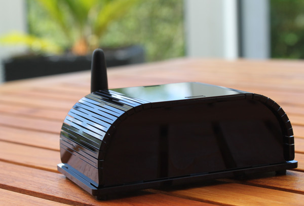
In our last blog entry we wrote about the first prototypes of the RED Brick. We found an error in the hardware design. One of the processor pins was mistakenly connected to ground. To sever the connection we used a drill bit that was a bit too large, nevertheless we were able to bring one of the RED Bricks to life. One week has passed and we have already gone big steps forward.

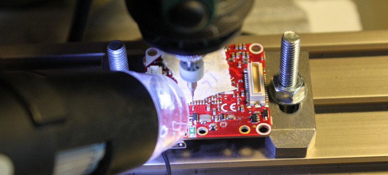
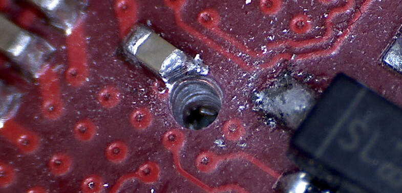
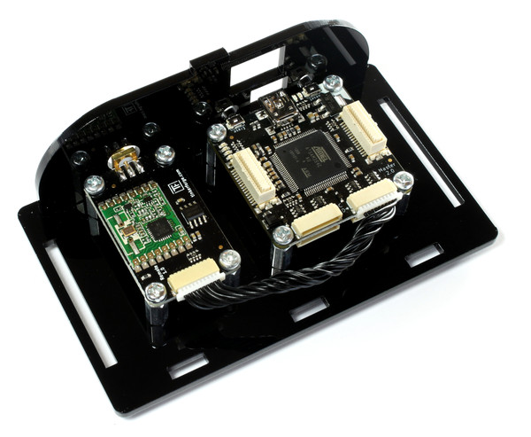
With the 0.3mm drill bits that arrived last week we were able to repair more RED Bricks. We used a professional xy-stage to position the drill bit correctly, but it was still a big challenge. For some of the Bricks we did damage traces of the 6-layer circuit board that are in proximity to the drill hole. In sum we now have six working RED Bricks.

U-Boot/Linux Image

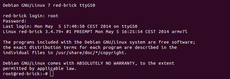
Most of our work until now went into U-Boot (bootloader) and the Linux image of the RED Brick. Some of the tasks have been to create a toolchain, write build scripts, implement hardware modifications (LEDs, DDR, interfaces), configure the image (language, hostname, etc) and similar. It is particularly time consuming to optimize boot time. We removed lots of daemons, drivers and similar that are not sensible on the RED Brick. The current boot time including graphical user interface is 45 seconds. We will still optimize that. Additionally to the full image with graphical user interface we are also working on a fast stripped down image without graphical user interface. In first tests we were able to reach a boot time of 15 seconds.

HDMI

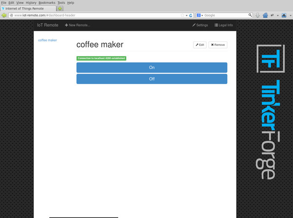
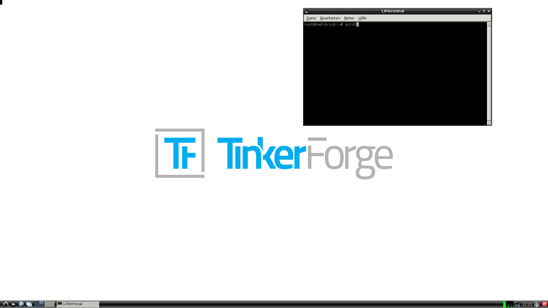
Since some of the HDMI signals are routed in direct proximity to the via that we had to drill out, HDMI does not work on all of the repaired RED Bricks. It seems we damaged the HDMI traces on those. The RED Bricks that have intact HDMI signals do have a working HDMI output: (Screenshot was taken directly on the RED Brick)

RED Brick Prototyp LXFE Screenshot

USB host

USB host is working too. Currently we are using USB WIFI dongles to connect the RED Brick to our local network.

RAM and heat testing

The connection of the DDR RAM to the processor is quite complex which means that it has to be tested thoroughly. We used the tool stress, which was able to heat up the RED Brick considerably. Stress uses up all of the available processor, RAM and SD card resources. We ran the test for several hours without a heatsink. While the RED Brick got hot, we could not observe any problems. Additionally we used memtester to run different tests on the RAM. These also couldn’t detect any problems. With sysbench and dd we were able to reach the expected performance goals. As far as we can tell there are no problems present with the connection, stability and performance of RAM, processor and SD card at all, they work exactly as expected.

It seems your finger crossing did work out, thanks!

What next?

There is still a huge amount of work that we have to put into the Linux image. We are also working hard to get the kernel drivers ready that are needed for communication between RED Brick and brickv. Over this interface it will be possible to configure the RED Brick and to transfer your own programs to the RED Brick. We will try to keep you informed in future blog posts!

RED Brick news

It has been a while since we announced the RED Brick here in the blog. We are working hard on the new Brick and are very happy to be able to give you a status update:

The circuit board order with clarification of technical details, the delivery time of one month and the long planning and preparation to populate the board had the consequence that we got the first populated prototype only on last Friday.

RED Brick prototype from different angles

We created our own debian image based on Sunxi Linux, which aims to support all Allwiner processors. Unfortunately we were not able to get it running at all with the prototype. So we already had to search for bugs in the very early stages of testing. Fortunately Allwinner processors have an easy method to directly speak with the processor, the FEL Interface. With FEL we were able to determine that the processor was not able to boot from the SD card. After days of searching we were finally able to identify the culprit. The processor has a JTAG interface, which can also be used for debugging. With two pins from the processor it is possible to configure on which pins the JTAG interface is available. Unfortunately the JTAG interface was configured to be active on the SD card interface pins. Because of that it was impossible for us to use an SD card. The processor has several SD card interfaces, which where exchanged during the hardware design phase. It seems that in the end we forgot to adjust the SD card interface accordingly.

The guilty pins are connected to a via directly below the (BGA) processor, so they are not reachable. Thus we tried to utilize one of the other SD card interfaces. Fortunately we have another SD card interface on the general purpuse/camera interface. After a little while of botch wiring we were able to connect them:

RED Brick prototype with botch wires

We were not able to get this SD card interface running. The datasheet of the processor did not help in this regard. We suspect that the processor is not able to boot from this secondary SD card interface at all. Alternatively we had electrical problems or we were not able to configure the image correctly.

Our only other hope was to somehow cut the JTAG configurations pins to get the correct SD card interface working. We already had all of the processors that we ordered populated. To populate new boards with a fixed circuit board would have taken a huge amount of time. Another possible solution would have been to desolder the processor (FBGA), cut the trace to the via, reball the processor and solder it on again. Unfortunately this wasn’t an feasible option because of the small distance between processor and RAM. As a last resort we drilled out the via that connects one of the pins to the ground layer to sever the connection. An internal pull-up of the processors now pulls the pin high.

But how do you drill a via that has an outer diameter of 0.3mm and a drill diameter of 0.15mm?

RED Brick prototype: Drilling

We tried it with this temporary setup. Unfortunately we only had a 0.5mm drill bit lying around. To position the drill on top of the via was not easy at all. We were only able to determine the drill depth by trial and error. The ground layer has a distance to the top layer (that is used by the processor) of 0.2mm. We needed to drill open this connection without drilling into the processor itself.

RED Brick Prototyp with hole

You can find the result of our destructive work in the image above. As we connected the RED Brick to the PC and waited for a sign of life the tension was at an all time high. You might imagine how joyful we were when we actually got a prompt:

RED Brick prototype prompt

What now?

We are currently testing the new Brick. We will have to show that it works absolutely stable. Tomorrow we will get new smaller drills, which we will use to bring more prototypes to life. After that we have to test all of the interfaces, such as HDMI and USB host. Then we will test the stack interface for the Bricks as well as the Master Extensions. In parallel our linux image is improved, there are still lots of customizations and optimizations needed. A big open task is to write a Linux kernel driver for communication with stack participants as well as (if necessary) changing the stack communication of all Bricks. The last and biggest open task is to implement the end user interface and the internal program execution.

We are super happy with the prototypes. All of the bugs in the hardware design that we found until now can be corrected with ease. Currently it looks like we will even be able to reuse the SMD stencil of the prototype for the mass production, since we don’t have to relocate any of the pads.

In the future we will write more blog entries about the RED Brick. We hope to be able to pass all of the remaining tests without changes. Cross your fingers!

New Starter Kit: Internet of Things

We just released our newest starter kit, the Starter Kit: Internet of Things. It is available for the introductory price of 49.99€.

https://www.tinkerforge.com/en/doc/_images/Kits/iot_on_table_600.jpg

The Internet of Things is an evolution of the Internet. It interconnects not only human and computer as before but also physical objects (things). Things can be home appliances, vehicles, industrial facilities or potentially everything we interact with daily.

https://www.tinkerforge.com/en/doc/_images/Kits/iot_half_open_600.jpg

The Starter Kit: Internet of Things basically consists consists of a Remote Switch Bricklet and a Master Brick. It allows to contol 433MHz actuators such as remotely controlled mains switches, remote dimmers and home automation components like automated blinds. We developed the web site iot-remote.com for the kit. It allows to control those acutators and the devices that are connected to them without any programming. The web sie uses the Tinkerforge Javascript Bindings, after you downloaded the web site for the first time you can use it in offline mode without an internet connection. Communication happens only between the controlling device, e.g. PC, smart phone or tablet and the actuator itself. The communication does not go through the Tinkerforge server or similar. If you don’t want to program anything yourself, you can easily use this web site to control your living room lights or other devices over the internet.

https://www.tinkerforge.com/en/doc/_images/Kits/iot_website_iot_remote_switch_600.jpg

If you want to implement your own project ideas you can use the Bindings for the Remote Switch Bricklet and as appropriate integrate other Tinkerforge modules. As an example a light or temperature dependent controlling with the Ambient Light or Temperature Bricklet is very easy to realize. The case of the starter kit does have additional holes for the Ethernet Extension, which can also be easily integrated. With the Ethernet Extension you can go without a Raspberry PI or similar that is used as a gateway.