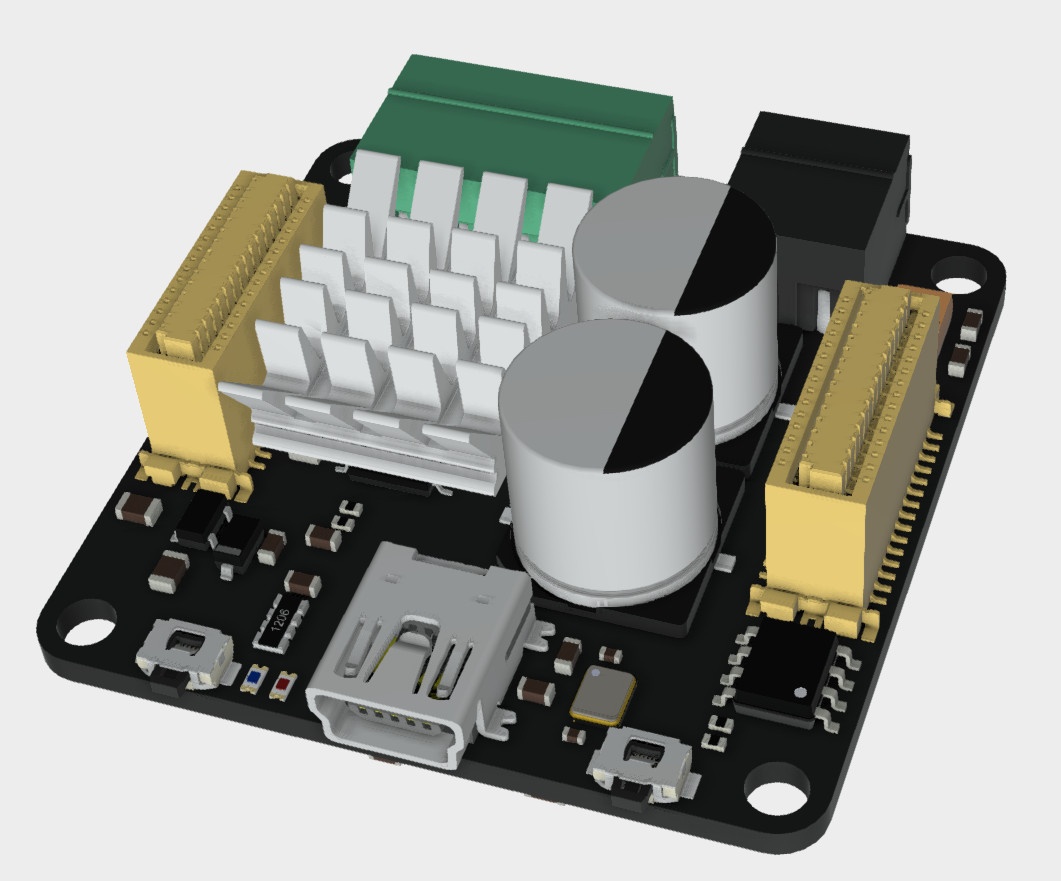
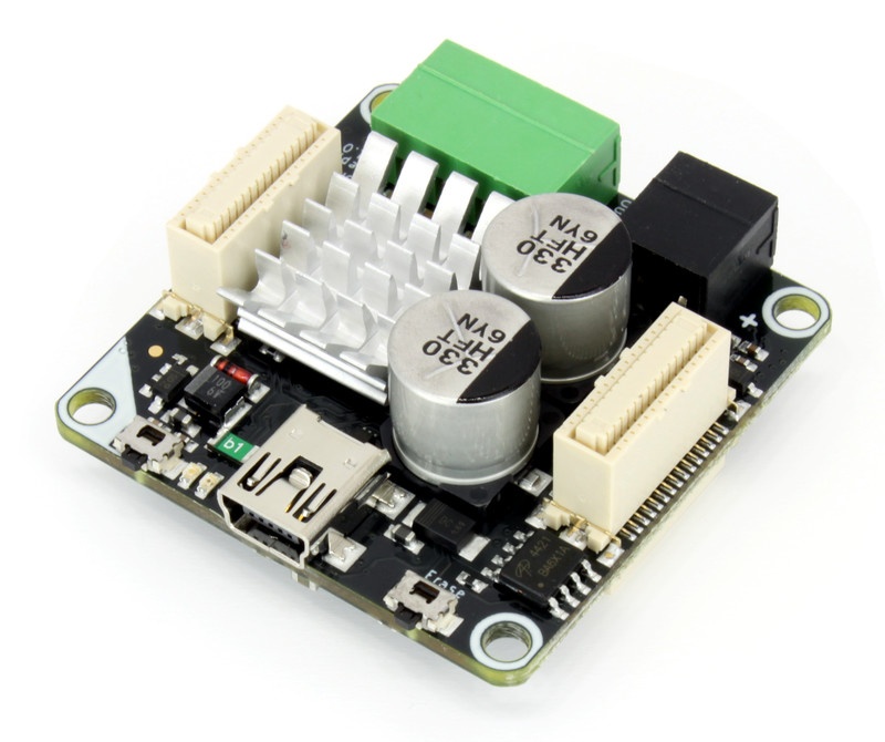
Blog

New homepage and server infrastructure

tl;dr: There will be a change of servers on Thursday January 12th 2017 starting at 08:00 Uhr. Please be ready for a downtime of up to 8-10 hours.

After we already wrote about changes in our system of building blocks yesterday, we want to introduce our new homepage today:

https://www.tinkerforge.com/static/img/_stuff/screenshot_new_hp_en.jpg

From a user perspective the content of the site does not change a lot. The frontpage as well as the explanation sites for new customers have been redesigned and improved. All of the other content stays essentially the same.

Surprisingly ~30% of our visitors come to our site via a smart phone or tablet. This is especially surprising since our products are normally used/programmed with a normal desktop PC. To deal with this fact the new homepage, particularity the shop and documentation, will now have a better usability for mobile devices.

From a technical perspective the new site has big changes. We will use a completely new CMS. This will make creation of new content and blog entries considerably easier for us. Furthermore, the domain “tinkerforge.com” will relocate to a new server. We will then have a physical separation between tinkerforge.com, mailserver, brickv.com/iot-remote.com and tinkerunity.org. If the visitor numbers increase further in the future, it will be easy to move parts of the new site or single databases to new servers.

To do the server and software switch we have to migrate our complete user database (this took about 4 hours in tests). Additionally we will have to change the DNS entry for tinkerforge.com to a new IP. Until this is known by all nameservers it will take some more time (~6 hours). Our mailserver will keep the old IP and it should be reachable for the whole time.

The server switch will be on Thursday January 12th 2017 starting at 08:00 Uhr. Please be ready for a downtime of up to 8-10 hours.

Outlook for 2017

After yesterdays review of last year we want to look into the future today.

We are happy to be able to announce a new generation of Bricklets, that we want to introduce today.

Currently each Bricklet has parts like sensors, analog-digital converters, LEDs, interface extensions etc. These parts are directly connected to the processor on the Bricks (through the Bricklet cable). This concept has the advantage, that simple Bricklets only need few parts. Every Bricklet has an EEPROM that saves the code for the Brick. This code is loaded by the Brick, written into its own flash and executed periodically. Because of this a Brick does not have to know each individual Bricklet. This allows the big variety of the different building blocks.

A disadvantage is, that the processor of the Brick has to run all of the Bricklet code as well as the code for the Brick functionality itself. Applications like a frequency counter or similar, that need to react permanently to a signal, are hard to realize. Another disadvantage is that the code of the Bricklets is only compatible to the SAM3 and SAM4 processors of Atmel. In the past we were confident that these processors are available for a long time. Since Microchip bought Atmel this is unfortunately not guaranteed anymore.

We will solve this problems with a new generation of Bricklets. The new Bricklets will have their own co-processors that only have two tasks:

  • To implement the Bricklet functionality,

  • and to communicate with the Brick.

The connected Brick has less load, since it only has to talk to the Bricklets and it can flexibly decide how to do so. The first new Bricklets of this generation will be the successor of the GPS Bricklet and a RS485 Bricklet:

https://www.tinkerforge.com/static/img/_stuff/gps_rs485.jpg

The current plan envisages that piece by piece all Bricklets are converted to a the new version with co-processor in a three year time frame.

After the conversion there is no dependence to a specific processor type anymore. All of the communication is done through well defined protocols. This would also allow something like a Raspberry PI shield that enables a RPI to directly talk to Bricklets.

We will talk more about the technical details of the co-processors and the utilized protocol. With this blog entry we would like to get some feedback in regards to a specific detail: The Bricklet connector.

Currently we use a 10 pole connector/socket from the JST SH series. The socket is functional and fits perfectly on the 4x4cm Bricks with regards to size. It has the disadvantage that the connector does not latch. If the connector is plugged in skewed, it is possible that the pins in the socket get bent (this can result in short circuits or similar).

For the communication with the new co-processor Bricklets we theoretically only need 7 wires. This would theoretically allow us to change the connector to one the is more comfortable to use. We are mostly looking at the GH series of connectors from JST:

https://www.tinkerforge.com/static/img/_stuff/jst_gh.jpg

This connector is latched. Additionally the pins in the socket are affixed to the socket casing dual-sided at the top and at the bottom. This allows for a better connection during vibrations (there are always two contact points available) und it is impossible to accidentally bend pins. The haptic of the connector is a big improvement. It even has a satisfactory “click-sound” if you plug it in.

The question now is: Would you rather have us switch to this new connector, or do you think it is better we keep the some connector with the complete system?

Scenario 1

  • The connectors remain the same for all of the building blocks.

  • The normal 10-pole to 10-pole Bricklet cable is compatible to the new and old generation of Bricklets.

Scenario 2

  • The connector on the new co-processor Bricklets is a 7-pole JST GH.

  • There are two Bricklet cable variants: 10-pole to 10-pole for the old Bricklets and 10-pole to 7-pole for the new generation of Bricklets.

  • After all Bricklets are converted (perhaps in 3 years) we will be able to change the connectors of the Bricks to the new 7-pol variant.

  • After that we only need 7-pole to 7-pole cables for the whole system.

In both scenarios the old Bricklets and the Bricklets of the new generation are completely compatible to each other and the old Bricks.

Which of the scenarios do you prefer? Please tell us your opinion in the Forum. Thanks!

Looking back at 2016

The year 2016 has concluded and we want to thank you for the exciting and successful year!

We released eight new Bricklets in 2016:

https://www.tinkerforge.com/en/doc/_images/Bricklets/bricklet_can_tilted_600.jpg

Additionally we now have the new WIFI Extension 2.0 as well as the Ethernet Extensions with and wihtout PoE.

https://www.tinkerforge.com/en/doc/_images/Extensions/extension_wifi2_hand_600.jpg

We visited three trade shows:

https://www.tinkerforge.com/static/img/_stuff/cebit_2016/cebit_2016_day1_4_small.jpg

Often customers come to us with a prototype made out of Bricks and Bricklets. They want to use the prototype as a starting point for a product that will be produced in bigger quantities. Internally we call these kinds of projects “industry projects”.

In 2016 we invested a large portion of our time in industry projects. Among others, we developed a system of sensors with controlling unit for a big German energy utility company. The system is used in electric car charging stations and intelligent street lamps.

For 2017 we set ourselves the target to work more on our system of building blocks. For that we recruited two additional full time employees at the end of 2016!

Tomorrow we will release a detailed list of future changes that we plan for the building blocks in the blog. We already look forward to your feedback regarding the changes.

Silent Stepper Brick

Today we want to write about the long story of development of the Silent Stepper Brick. Our current Stepper Brick generates, like most stepper drivers, audible high-pitched noises when a motor is driven. The reason for these noises lays in the motor inductance together with the current control. In full step mode the noise is usually louder then if the motor is driven in micro-step mode (1/4, 1/8, …). Since there are applications in which this audible high-pitched noise is undesirable, we decided to work on a quieter alternative. The Silent Stepper Brick

Development part 1

https://www.tinkerforge.com/static/img/_stuff/silent_stepper.jpg

The size of the Silent Stepper Brick is pre-determined as 4x4cm. If you exclude the space for the board-to-board connectors, the Bricklet connectors and the microcontroller, it is clear that we can only use an integrated driver solution. The TMC2100 is a integrated driver IC that supports different kinds of current control and a silent mode (Stealth Chop). The driver supports a maximum phase current of 1.2A and up to 256 micro steps. Thus stepper motors can be spun precisely and the maximum current fits to the stepper motors that we have in our shop.

We started the development of a first prototype with a TMC2100 driver IC. We found out that the prototype had problems with high motor speeds: The torque would suddenly collapse and the motor could stop abruptly. After a long search we found two reasons for this:

  1. Our layout of the prototype wasn’t optimal, so we had to develop a new one.

  2. Stepper motors have a resonance frequency. If the motor spins at the right frequency it can become unstable. Usually it is easiest to just accelerate quickly trough this frequency. Since we had the additional problems with the layout, we first didn’t realize that we just found a normal behavior and there was no other design error.

After we overcame these problems and were nearly done with the development, there was a price adjustment: Beside the TMC2100 there is also the TMC2130. This driver has many more settings to play around with and additional exciting features. When we started the development the TMC2130 was significantly more expensive then the 2100, so we decided to use the simpler TMC2100. Now suddenly both drivers had nearly the same price, thus we decided to use the TMC2130. We had basically had to start with the development from scratch…

The TMC2100 has a simple interface. It is configurable over a few pins, which results in few settings. The TMC2130 on the other hand has a SPI interface and quite a number of different adjustment possibilities. We had to start the software from scratch and learn about all of the different settings. Since we already had a Stepper Brick the new Silent Stepper Brick did not have the highest priority, so this whole back and force did take a lot of time. The TMC2130 does have a internal clock that is used for the current control etc. The internal clock is however quite inaccurate and the accuracy is highly temperature dependent. In tests we found that the behavior of the driver changed slightly with changing temperatures, which we found unacceptable. We could of course easily provide a precise clock signal with our main processor, but we had to make yet another prototype for this!

EMC Laboratory

During the development of our products we routinely check for electromagnetic compliance. Since the design and the software has a big influence on this, we can only do the tests at the end of the development phase. Clock signals, high frequency buses etc have big influence.

We often visit a professional EMC Laboratory, but since these measurements can be quite expensive as well as time intensive, we now set up our own small EMC pre-compliance testing laboratory.

https://www.tinkerforge.com/static/img/_stuff/laboratory1.jpghttps://www.tinkerforge.com/static/img/_stuff/laboratory2.jpg

We use a Rigol DSA815 spectrum analyzer, a TEM cell and a big metal case to shield the device under test. With this set up we can’t guarantee the same measurement precision as a real EMC laboratory. However, we can usually still find out if a device exceeds the regulatory radiation limits. This way we can find EMC problems oftentimes before we do the real tests in a EMC laboratory.

A spectrum analyzer shows the amplitude for a specified band of frequencies, i.e. the strength of the electromagnetic radiation for individual frequencies. Without any shielding you will measure radio stations, gsm networks etc additionally to your device under test. Thus it is important that we try to shield the whole device during the testing as best as possible.

If a trace on the circuit board carries a signal with a specific frequency, you may find multiples of this frequency with the spectrum analyzer. The following photo shows the multiples of the Frequency 12.8 MHz.

https://www.tinkerforge.com/static/img/_stuff/spectrum_peak.jpg

If you don’t immediately now which part of the circuit might create this frequency, you can use so called near-field probes. These can be used to measure the radiation locally, even down to a single trace or a single pin of a IC.

The interference can have different reasons. It can be a bad layout, steep signal edges, problems with grounding etc. Sometimes it is possible to reduce the radiation with a simple change of a part value (for example a different resistance for a series resistor in a signal path). Often there is no easy fix and the layout has to be revised.

Development part 2

Unfortunately we didn’t write about our measurements of electromagnetic interference without reason. We finished the development of the Silent Stepper Brick in time to be able to produce them this year. As a last step we wanted to do some EMC measurements. We used our own small laboratory for a first test and the measurement results were underwhelming to say the least.

We could easily see the multiples of the clock signal that we connected from the processor to the TMC2130 (see image above). The peaks seem to be barely below the limit, but the risk to go to the EMC laboratory with the board was just too high.

We did already have a series resistor in the trace of the clock line to be able to control the slew rate (edge steepness) of the signal. Unfortunately we were not able to find any resistor value that would significantly decrease the radiation problems. Thus we had to order another prototype. Each prototype will cost about two weeks of time with an additional 1/2 - 1 day time investment to actually build the prototype (including finding and removing solder errors etc).

With the new prototype we wanted to be on the safe side, so we ordered two variants: one with a better clock signal routing and more filter possibilities and one with a completely modified ground layer layout. During the tests of the new prototypes we found out that the new ground layer idea did not help (in fact the results were worse). Fortunately the additional filtering on the other prototype did the trick! We could now be very sure that we would satisfy the regulatory electromagnetic radiation limits.

In sum we made 8 prototypes during the development process of the Silent Stepper Brick:

https://www.tinkerforge.com/static/img/_stuff/silent_stepper_brick_8_prototypes.jpg

What now?

The circuit boards will be ordered next week. Because of Christmas and New Year the delivery will take longer then normal, but we are pretty sure that you will be able to buy Silent Stepper Bricks in the beginning of march. You can look forward for a nice comparison video of the new and old Stepper Brick.

WIFI Extension Firmware 2.0.1

Firmware Version 2.0.1 for the WIFI Extension 2.0 is now available.

The new firmware of the WIFI Extension has now a web interface. You can use it to check the state of the WIFI Extension and to set the configuration (similar to Brick Viewer).

https://www.tinkerforge.com/de/doc/_images/Extensions/extension_wifi2_web_interface_status.jpghttps://www.tinkerforge.com/de/doc/_images/Extensions/extension_wifi2_web_interface_settings.jpg

Additionally there are small bug fixes. In firmware version 2.0.0 you couldn’t use Access Point mode together with static IP, this is fixed now.

The next firmware version of the WIFI Extension will have mesh-network functionality, so stay tuned!