- Getting Started
- Hardware
- Bricks
- Bricklets
- Accelerometer Bricklet 2.0
- Air Quality Bricklet
- Ambient Light Bricklet 3.0
- Analog In Bricklet 3.0
- Analog Out Bricklet 3.0
- Barometer Bricklet
- Barometer Bricklet 2.0
- Breakout Bricklet
- CAN Bricklet
- CAN Bricklet 2.0
- CO2 Bricklet 2.0
- Color Bricklet
- Color Bricklet 2.0
- Compass Bricklet
- DC Bricklet 2.0
- Distance IR Bricklet
- Distance IR Bricklet 2.0
- Distance US Bricklet 2.0
- DMX Bricklet
- Dual Button Bricklet 2.0
- Dust Detector Bricklet
- E-Paper 296x128 Bricklet
- Energy Monitor Bricklet
- GPS Bricklet 2.0
- GPS Bricklet 3.0
- Hall Effect Bricklet
- Hall Effect Bricklet 2.0
- Humidity Bricklet 2.0
- IMU Bricklet 3.0
- Industrial Analog Out Bricklet 2.0
- Industrial Counter Bricklet
- Industrial Digital In 4 Bricklet 2.0
- Industrial Digital Out 4 Bricklet
- Industrial Digital Out 4 Bricklet 2.0
- Industrial Dual 0-20mA Bricklet
- Industrial Dual 0-20mA Bricklet 2.0
- Industrial Dual AC In Bricklet
- Industrial Dual AC Relay Bricklet
- Industrial Dual Analog In Bricklet 2.0
- Industrial Dual Relay Bricklet
- Industrial PTC Bricklet
- Industrial Quad Relay Bricklet 2.0
- IO-16 Bricklet
- IO-16 Bricklet 2.0
- IO-4 Bricklet 2.0
- Isolator Bricklet
- Joystick Bricklet
- Joystick Bricklet 2.0
- Laser Range Finder Bricklet 2.0
- LCD 128x64 Bricklet
- LCD 20x4 Bricklet
- LED Strip Bricklet 2.0
- Line Bricklet
- Linear Poti Bricklet
- Linear Poti Bricklet 2.0
- Load Cell Bricklet 2.0
- Motion Detector Bricklet 2.0
- Motorized Linear Poti Bricklet
- Multi Touch Bricklet
- Multi Touch Bricklet 2.0
- NFC Bricklet
- OLED 128x64 Bricklet 2.0
- OLED 64x48 Bricklet
- One Wire Bricklet
- Outdoor Weather Bricklet
- Particulate Matter Bricklet
- Performance DC Bricklet
- Piezo Speaker Bricklet
- Piezo Speaker Bricklet 2.0
- Real-Time Clock Bricklet
- Real-Time Clock Bricklet 2.0
- Remote Switch Bricklet 2.0
- RGB LED Bricklet 2.0
- RGB LED Button Bricklet
- Rotary Encoder Bricklet 2.0
- Rotary Poti Bricklet
- Rotary Poti Bricklet 2.0
- RS232 Bricklet
- RS232 Bricklet 2.0
- RS485 Bricklet
- Segment Display 4x7 Bricklet
- Segment Display 4x7 Bricklet 2.0
- Servo Bricklet 2.0
- Silent Stepper Bricklet 2.0
- Solid State Relay Bricklet 2.0
- Sound Intensity Bricklet
- Sound Pressure Level Bricklet
- Temperature Bricklet
- Temperature Bricklet 2.0
- Temperature IR Bricklet 2.0
- Thermal Imaging Bricklet
- Thermocouple Bricklet 2.0
- Tilt Bricklet
- UV Light Bricklet 2.0
- Voltage/Current Bricklet 2.0
- XMC1400 Breakout Bricklet
- Master Extensions
- Power Supplies
- Discontinued Products
- Timeline
- Software
- Kits
- Embedded Boards
- Specifications
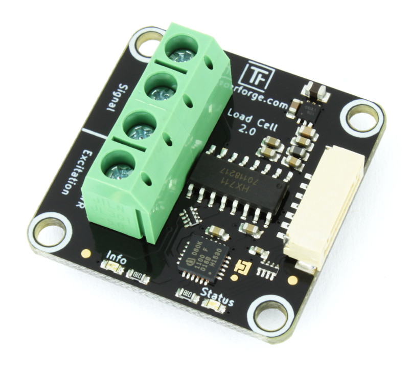
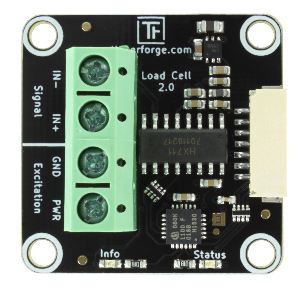
Load Cell Bricklet 2.0

Features
Measures output of load cells
24bit ADC for high resolution
Up to 80 weight measurements per second
Description
The Load Cell Bricklet 2.0 can be used to extend the features of Bricks by the capability to measure load cells. Only a single known weight is required to calibrate the load cell. It is possible to measure weight differences of few grams in objects that weigh many kilograms.
Load cells with different maximum weights are available in the shop:
The Bricklet has the standard status LED and an additional info LED that can be turned on trough the API, e.g. to show that a weight measurement is in range.
This Bricklet ist not galvanically isolated to the Tinkerforge system. This means that there is a direct electrical connection between the terminals of the Bricklet and the rest of the system. Dependent of the application this can lead to undesired connections, ground loops or short circuits. These problems can be prevented by using the Bricklet together with a Isolator Bricklet.
Technical Specifications
Property |
Value |
|---|---|
Sensor |
HX711 |
Current Consumption |
54mW (10.8mA at 5V) |
Resolution |
24bit |
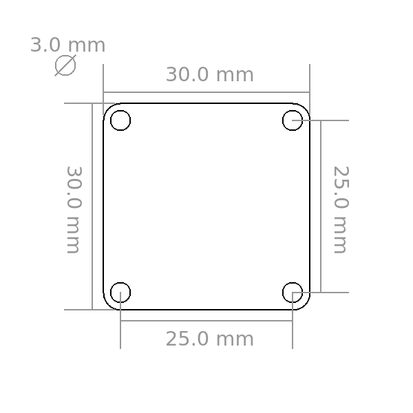
Dimensions (W x D x H) |
30 x 30 x 14mm (1.18 x 1.18 x 0.55") |
Weight |
7.3g |
Resources
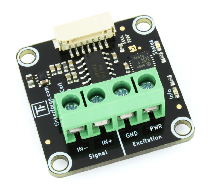
Connectivity
The Load Cell Bricklet 2.0 has four terminals. The PWR and GND terminals are for the excitation voltage and the IN+ and IN- terminals are for the signal measurement.
A typical load cell will have four or five wires. Check the specification of your load cell for its pinout and connect it according to the table below.
Connection |
Terminal |
Possible Wire Colors |
|---|---|---|
Excitation + |
PWR |
red |
Excitation - |
GND |
black, yellow |
Signal + |
IN+ |
green, blue |
Signal - |
IN- |
white |
Test your Load Cell Bricklet 2.0
To test a Load Cell Bricklet 2.0 you need to have Brick Daemon and Brick Viewer installed. Brick Daemon acts as a proxy between the USB interface of the Bricks and the API bindings. Brick Viewer connects to Brick Daemon. It helps to figure out basic information about the connected Bricks and Bricklets and allows to test them.
Connect the Load Cell Bricklet 2.0 to a Brick with a Bricklet Cable. Additionally connect and calibrate a load cell.
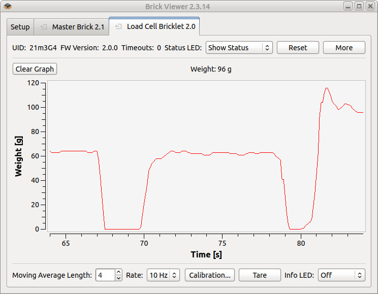
If you connect the Brick to the PC over USB, you should see a new tab named "Load Cell Bricklet 2.0" in the Brick Viewer after a moment. Select this tab. If everything went as expected you can now see the weight in gram and a graph that shows the weight over time.
After this test you can go on with writing your own application. See the Programming Interface section for the API of the Load Cell Bricklet 2.0 and examples in different programming languages.
Calibration
The Load Cell Bricklet 2.0 has to be calibrated for the connected load cell and the specific setup.
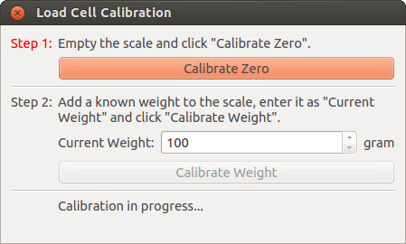
Connect a load cell to the Bricklet as described above. Then start Brick Viewer and click the "Calibration" button on the "Load Cell Bricklet 2.0" tab. With no weight on the load cell, click the "Calibrate Zero" button. Now put a known weight on the load cell, enter the known weight in gram as the "Current Weight", then click the "Calibrate Weight" button.
Now the Load Cell Bricklet 2.0 is calibrated for the connected load cell and the specific setup.
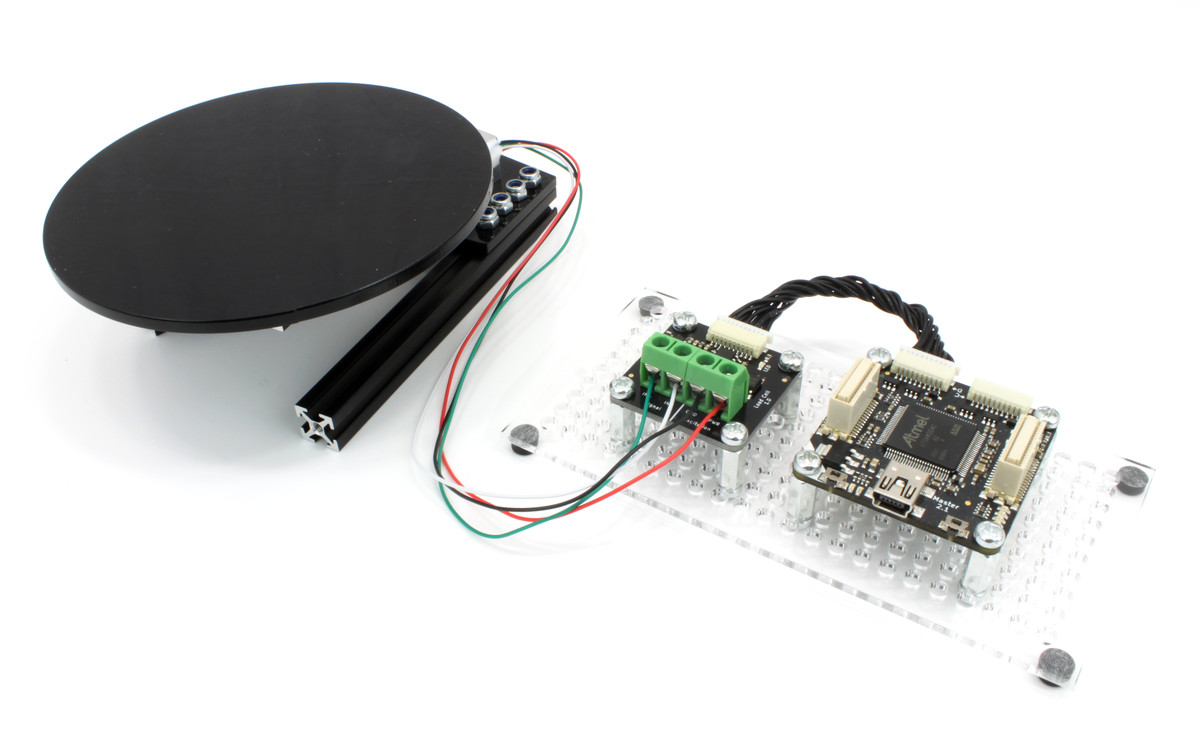
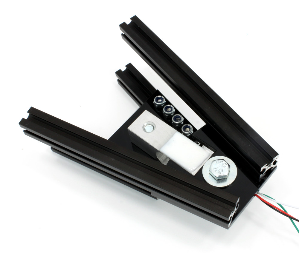
Scale Kit
The Scale Kit is build from MakerBeam, a 1kg Load Cell and laser cut plastic parts. It is available in the Tinkerforge shop, but you can also just use the description to get an idea on how to mount a load cell in general.
Building up the Scale Kit is pretty easy. Start by removing the protective foil from the plastic parts (there is foil on both sides).
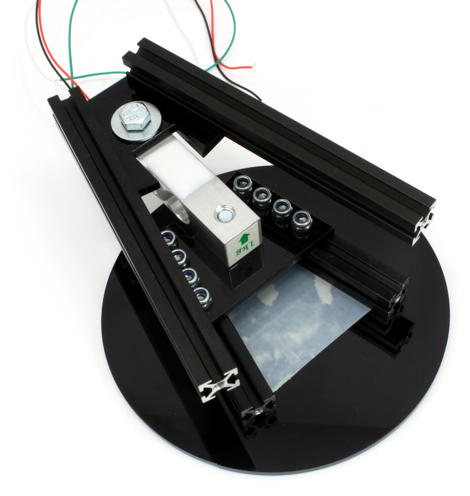
Screw the 60mm MakerBeam and the load cell to the top plastic part. Ensure to screw the load cell with the arrow side to the plastic part and that the arrow is pointing away from the plastic part.
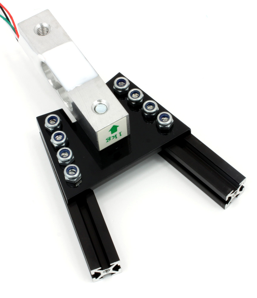
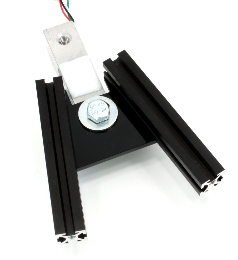
Screw the 100mm MakerBeam and the load cell to the bottom plastic part.
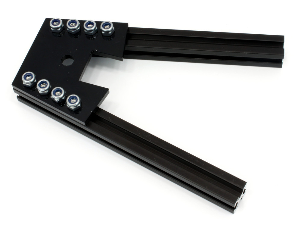
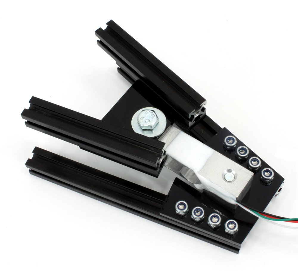
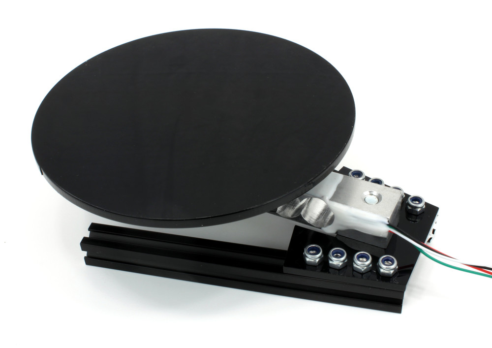
Use the double sided tape to attach the round plate to the 60mm MakerBeam.
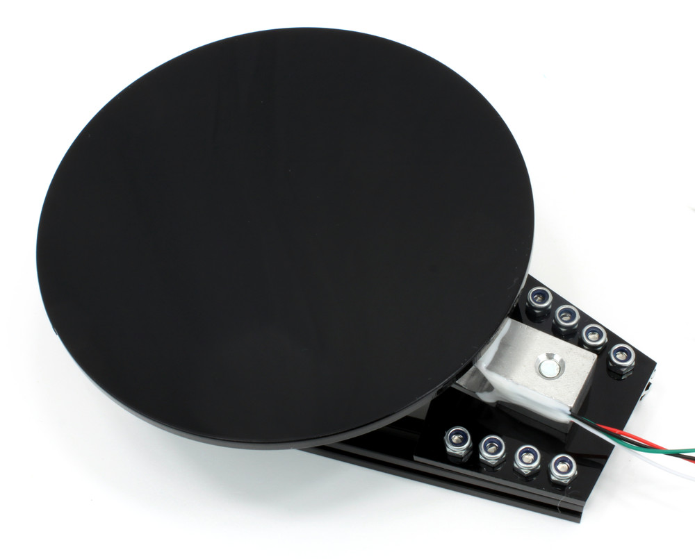
Mechanical construction done! Finally, connect the load cell to the Bricklet as described in the connectivity section.
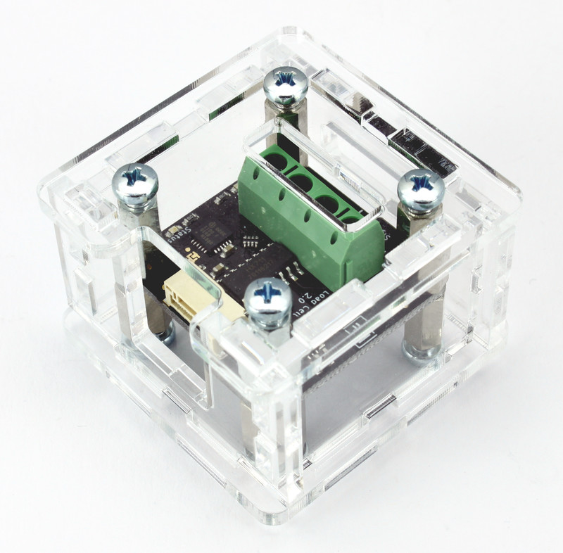
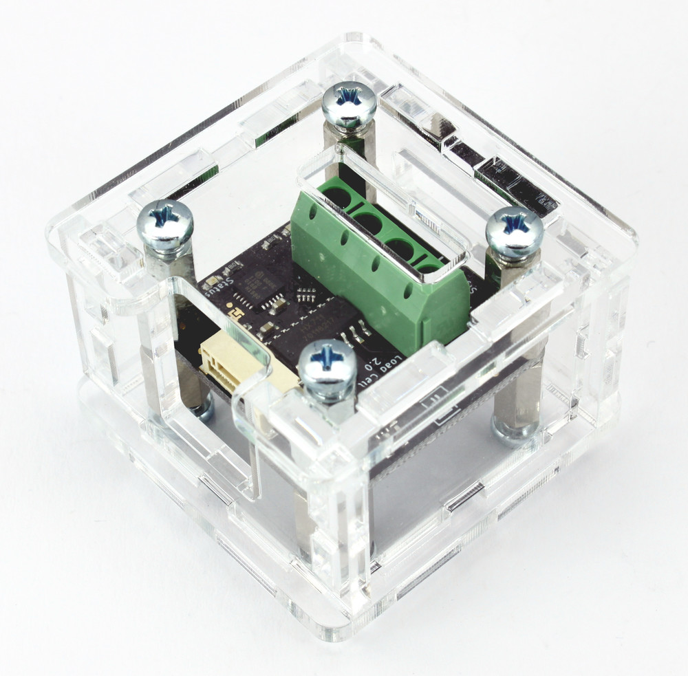
Case
A laser-cut case for the Load Cell Bricklet 2.0 is available.
The assembly is easiest if you follow the following steps:
Screw spacers to the Bricklet,
screw bottom plate to bottom spacers,
build up side plates,
plug side plates into bottom plate and
screw top plate to top spacers.
Below you can see an exploded assembly drawing of the Load Cell Bricklet case:
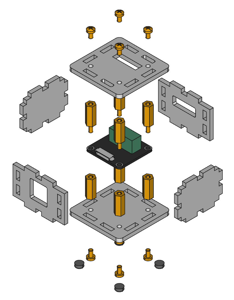
Hint: There is a protective film on both sides of the plates, you have to remove it before assembly.
Programming Interface
See Programming Interface for a detailed description.
Language |
API |
Examples |
Installation |
|---|---|---|---|
C/C++ |
|||
C/C++ for Microcontrollers |
|||
C# |
|||
Delphi/Lazarus |
|||
Go |
|||
Java |
|||
JavaScript |
|||
LabVIEW |
|||
Mathematica |
|||
MATLAB/Octave |
|||
MQTT |
|||
openHAB |
|||
Perl |
|||
PHP |
|||
Python |
|||
Ruby |
|||
Rust |
|||
Shell |
|||
Visual Basic .NET |
|||
TCP/IP |
|||
Modbus |