- Getting Started
- Hardware
- Bricks
- Bricklets
- Accelerometer Bricklet 2.0
- Air Quality Bricklet
- Ambient Light Bricklet 3.0
- Analog In Bricklet 3.0
- Analog Out Bricklet 3.0
- Barometer Bricklet
- Barometer Bricklet 2.0
- Breakout Bricklet
- CAN Bricklet
- CAN Bricklet 2.0
- CO2 Bricklet 2.0
- Color Bricklet
- Color Bricklet 2.0
- Compass Bricklet
- DC Bricklet 2.0
- Distance IR Bricklet
- Distance IR Bricklet 2.0
- Distance US Bricklet 2.0
- DMX Bricklet
- Dual Button Bricklet 2.0
- Dust Detector Bricklet
- E-Paper 296x128 Bricklet
- Energy Monitor Bricklet
- GPS Bricklet 2.0
- GPS Bricklet 3.0
- Hall Effect Bricklet
- Hall Effect Bricklet 2.0
- Humidity Bricklet 2.0
- IMU Bricklet 3.0
- Industrial Analog Out Bricklet 2.0
- Industrial Counter Bricklet
- Industrial Digital In 4 Bricklet 2.0
- Industrial Digital Out 4 Bricklet
- Industrial Digital Out 4 Bricklet 2.0
- Industrial Dual 0-20mA Bricklet
- Industrial Dual 0-20mA Bricklet 2.0
- Industrial Dual AC In Bricklet
- Industrial Dual AC Relay Bricklet
- Industrial Dual Analog In Bricklet 2.0
- Industrial Dual Relay Bricklet
- Industrial PTC Bricklet
- Industrial Quad Relay Bricklet 2.0
- IO-16 Bricklet
- IO-16 Bricklet 2.0
- IO-4 Bricklet 2.0
- Isolator Bricklet
- Joystick Bricklet
- Joystick Bricklet 2.0
- Laser Range Finder Bricklet 2.0
- LCD 128x64 Bricklet
- LCD 20x4 Bricklet
- LED Strip Bricklet 2.0
- Line Bricklet
- Linear Poti Bricklet
- Linear Poti Bricklet 2.0
- Load Cell Bricklet 2.0
- Motion Detector Bricklet 2.0
- Motorized Linear Poti Bricklet
- Multi Touch Bricklet
- Multi Touch Bricklet 2.0
- NFC Bricklet
- OLED 128x64 Bricklet 2.0
- OLED 64x48 Bricklet
- One Wire Bricklet
- Outdoor Weather Bricklet
- Particulate Matter Bricklet
- Performance DC Bricklet
- Piezo Speaker Bricklet
- Piezo Speaker Bricklet 2.0
- Real-Time Clock Bricklet
- Real-Time Clock Bricklet 2.0
- Remote Switch Bricklet 2.0
- RGB LED Bricklet 2.0
- RGB LED Button Bricklet
- Rotary Encoder Bricklet 2.0
- Rotary Poti Bricklet
- Rotary Poti Bricklet 2.0
- RS232 Bricklet
- RS232 Bricklet 2.0
- RS485 Bricklet
- Segment Display 4x7 Bricklet
- Segment Display 4x7 Bricklet 2.0
- Servo Bricklet 2.0
- Silent Stepper Bricklet 2.0
- Solid State Relay Bricklet 2.0
- Sound Intensity Bricklet
- Sound Pressure Level Bricklet
- Temperature Bricklet
- Temperature Bricklet 2.0
- Temperature IR Bricklet 2.0
- Thermal Imaging Bricklet
- Thermocouple Bricklet 2.0
- Tilt Bricklet
- UV Light Bricklet 2.0
- Voltage/Current Bricklet 2.0
- XMC1400 Breakout Bricklet
- Master Extensions
- Power Supplies
- Discontinued Products
- Timeline
- Software
- Kits
- Embedded Boards
- Specifications
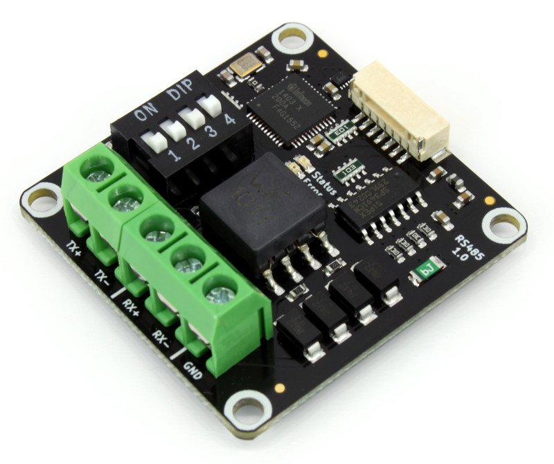
RS485 Bricklet

Features
Supports low-level RS485 as well as Modbus RTU master/slave
Modbus RTU implementation is fully compliant for reading and writing of coils and registers
Supports full- and half-duplex
Configurable baudrate, parity, stop bits and word length
Switchable 120 Ohm termination
Description
The RS485 Bricklet can be used to extend the features of Bricks by the capability to send and receive differential data with RS-485.
It supports full- and half-duplex and has configurable termination.
You can use the Bricklet in RS485, Modbus RTU master and Modbus RTU slave mode.
In RS485 mode you can send and receive arbitrary data. The Modbus modes are fully Modbus compliant. In Modbus RTU master mode you can write and read any coils/registers from a slave. In Modbus RTU slave mode you can provide data for coil/register reads and you receive the data that a Modbus master writes to the coils/registers.
This Bricklet ist not galvanically isolated to the Tinkerforge system. This means that there is a direct electrical connection between the terminals of the Bricklet and the rest of the system. Dependent of the application this can lead to undesired connections, ground loops or short circuits. These problems can be prevented by using the Bricklet together with a Isolator Bricklet.
Technical Specifications
Property |
Value |
|---|---|
Current Consumption |
64mW (12.8mA at 5V, idle) |
Baudrate |
100 - 2000000 baud |
Parity |
none / odd / even |
Stop bits |
1 / 2 |
Word length |
5 / 6 / 7 / 8 |
Duplex |
half / full |
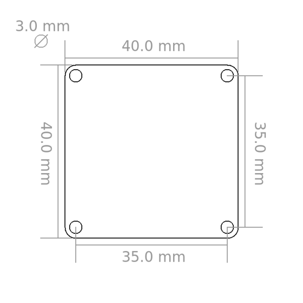
Dimensions (W x D x H) |
40 x 40 x 14mm (1.57 x 1.57 x 0.55") |
Weight |
13g |
Resources
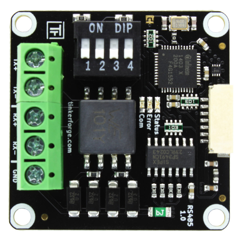
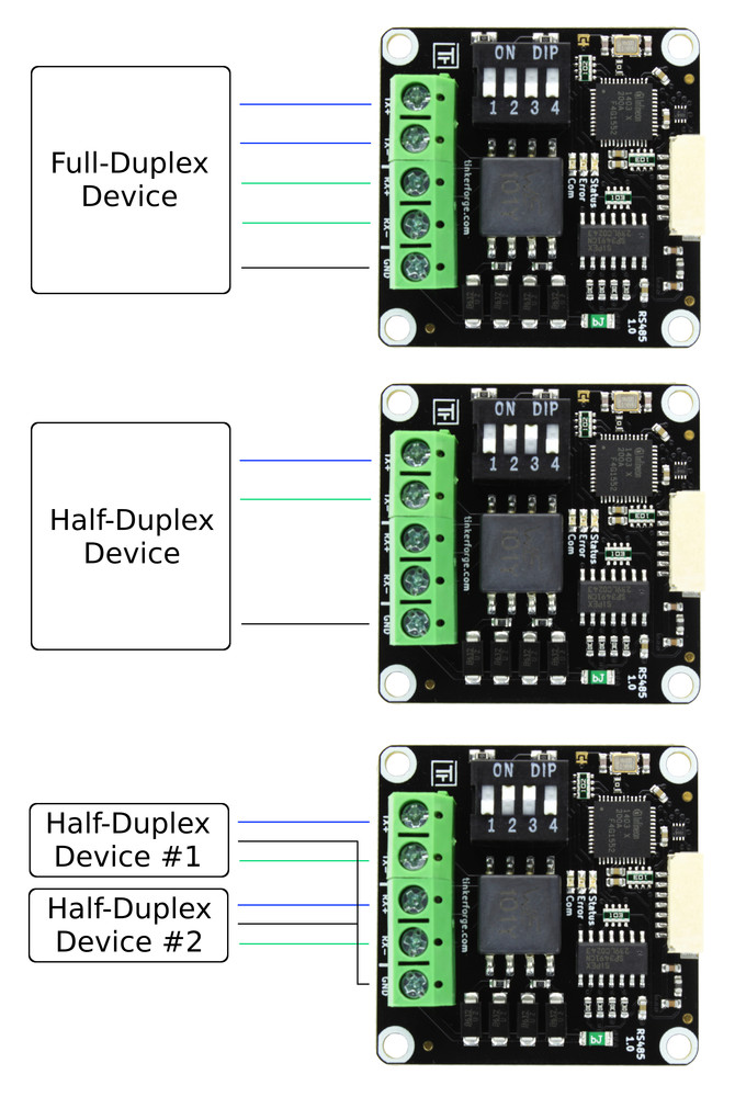
Connectivity
In full-duplex mode you have to connect TX+, TX-, RX+, RX- and GND.
In half-duplex mode TX+ / RX+ and TX- / RX- are shorted, so you can connect either TX+ / TX- / GND or RX+ / RX- / GND. You can also use this to chain-connect other devices.
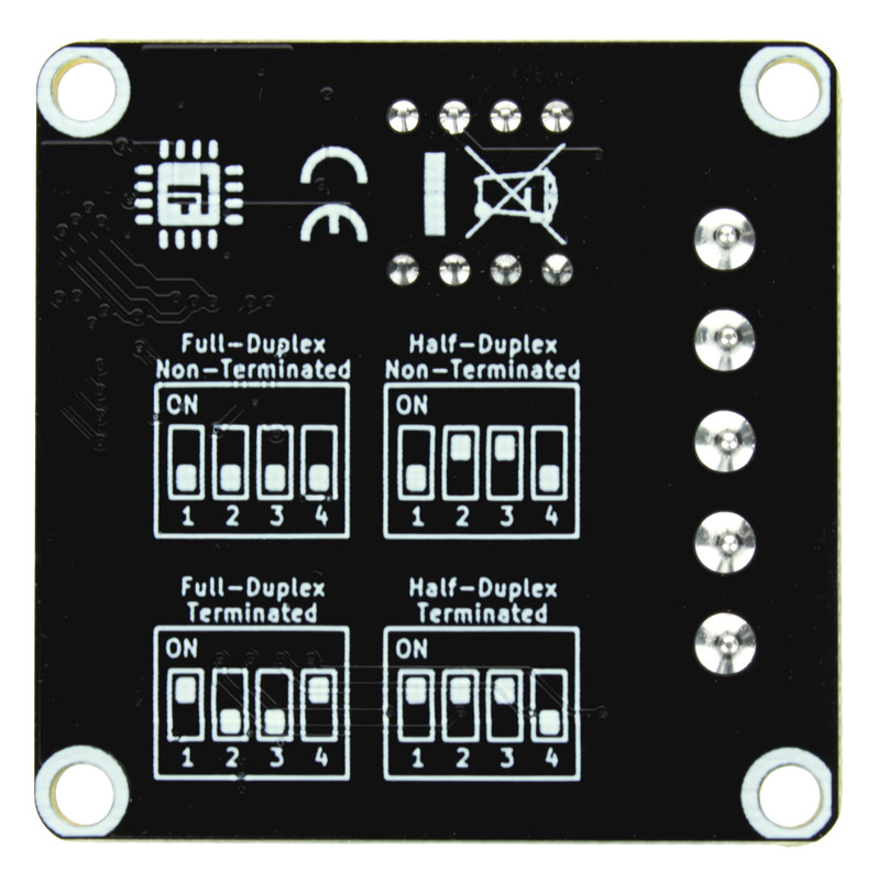
Duplex and Termination configuration
The DIP switches on the Bricklet can be used to configure duplex and termination configuration.
You can configure between Full-Duplex and Half-Duplex and you can enable or disable a 120 Ohm termination resistor.
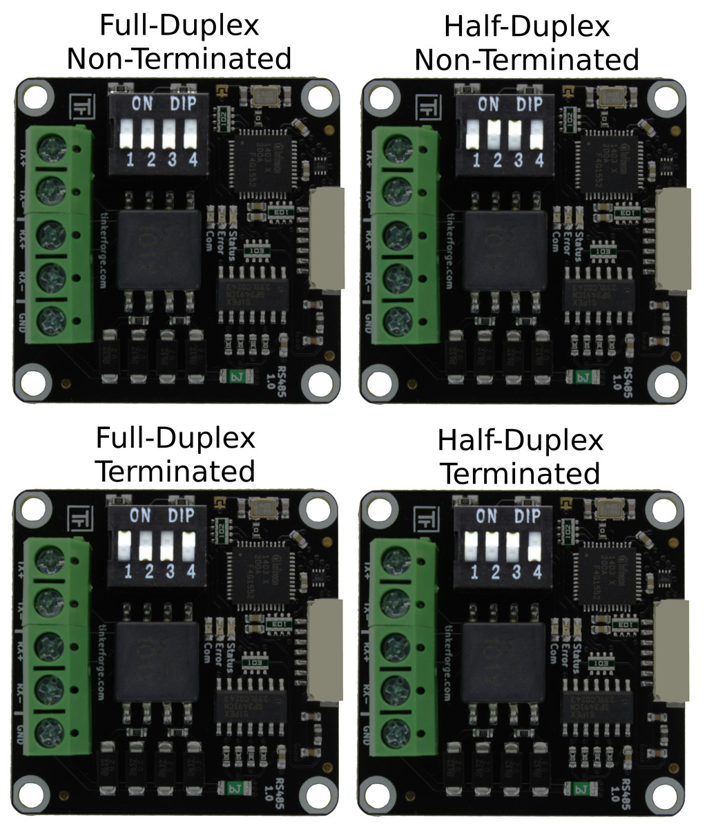
A legend of the different configuration possibilities can also be found in the bottom of the Bricklet.
DIP switch 1 connects a 120 Ohm termination resistor between TX+ and TX-
DIP switch 2 connects TX+ to RX+ for Half-Duplex operation
DIP switch 3 connects TX- to RX- for Half-Duplex operation
DIP switch 4 connects a 120 Ohm termination resistor between RX+ and RX-
The total termination resistance in a single bus has to be 120 Ohm. Because of this only DIP switch 1 is on and DIP switch 4 stays off in Half-Duplex terminated mode. Otherwise both 120 Ohm termination resistors would be connected in parallel due to the TX+/RX+ and TX-/RX- connections resulting in 60 Ohm total termination resistance.
Modbus RTU Functions
The Bricklet can be configured to operate on Modbus RTU master/slave mode. In this mode Modbus specific protocol messages can be sent and received. A Modbus master can send a request to a Modbus slave connected to the bus. These Modbus functions are based on callbacks.
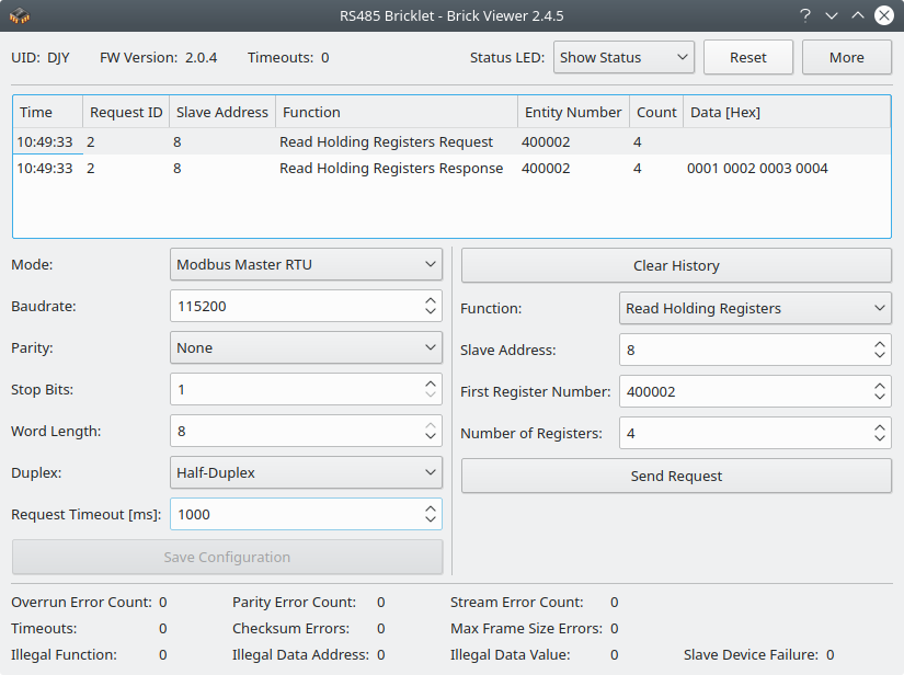
To better understand the general concept a scenario is described. In this scenario two RS485 Bricklets are present on the bus. One operating in Modbus master mode and the other in Modbus slave mode. The Modbus master wants to read 4 registers starting with the register 400002 (e.g. the second holding register) from Modbus slave at address 8:
The master registers the modbus_master_read_holding_registers_response callback which will be called when the slave sends a response to the master. The Bricklet that is operating in slave mode registers the modbus_slave_read_holding_registers_request callback which will be called when a corresponding request is received.
The master calls the function modbus_master_read_holding_registers. Parameters of this function specifies the slave address, the number of the first register and the number of registers to read. The prefix digit 4, that identifies the register as holding register, is implicit and has to be omitted. This function sends the request on the bus.
On the slave side the registered callback is invoked with the parameters which specifies that the master wants to read 4 holding registers starting from register 2.
The slave calls the function modbus_slave_answer_read_holding_registers_request with the requested data which sends the response on the bus.
Upon receiving the response from the slave the modbus_master_read_holding_registers_response callback is called on the master side with the data provided by the slave.
For details of these functions refer to the programming interface section.
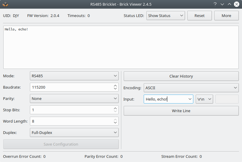
All of the available Modbus functions can also be used in Brick Viewer:
Test your RS485 Bricklet
To test a RS485 Bricklet you need to have Brick Daemon and Brick Viewer installed. Brick Daemon acts as a proxy between the USB interface of the Bricks and the API bindings. Brick Viewer connects to Brick Daemon. It helps to figure out basic information about the connected Bricks and Bricklets and allows to test them.
Connect the RS485 Bricklet to a Brick with a Bricklet Cable. Connect the RX+ to the TX+ pin and the RX- to the TX- pin with two cables to make the Bricklet read back its own output. Configure the DIP switches to full duplex mode, with half termination (1: on, 2: off, 3: off, 4: off). This is a diversion from the normal Full-Duplex terminated setting, because the Bricklet talks back to itself for this test. Otherwise the total termination resistance would be 60 Ohm instead of 120 Ohm if both 120 Ohm termination resistors would be connected in parallel.
If you connect the Brick to the PC over USB, you should see a new tab named "RS485 Bricklet" in the Brick Viewer after a moment. Select this tab. Set the mode to RS485 and the duplex option to full duplex and then click Save Configuration. If everything went as expected you can now type some text into the input editbox and hit enter. The same text should then show up in the textarea above.
After this test you can go on with writing your own application. See the Programming Interface section for the API of the RS485 Bricklet and examples in different programming languages.
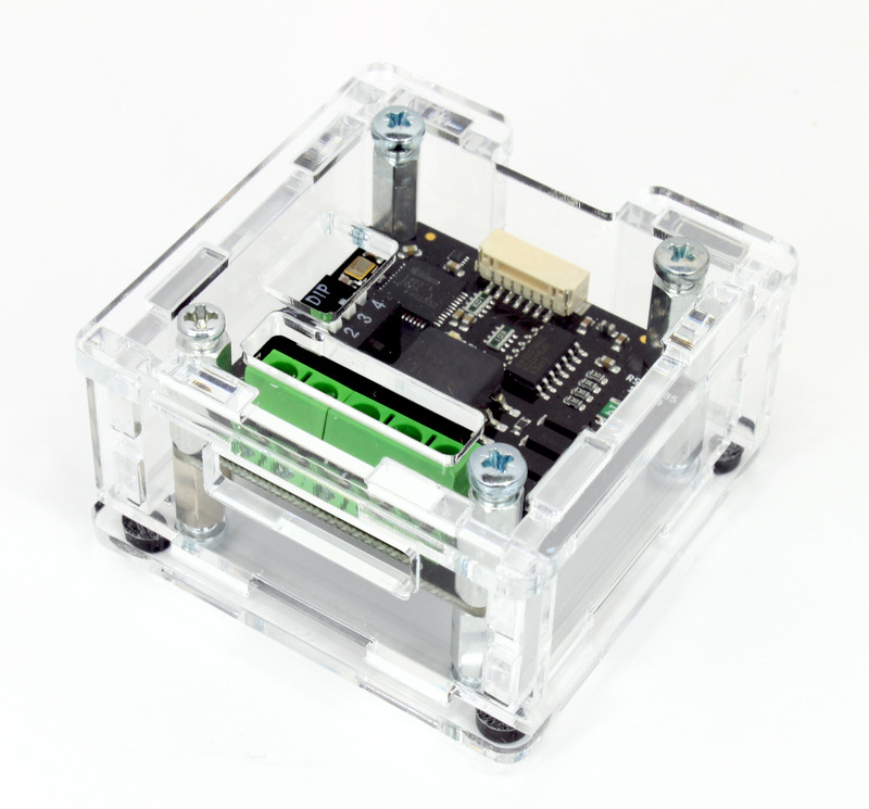
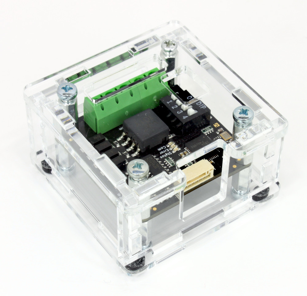
Case
A laser-cut case for the RS485 Bricklet is available.
The assembly is easiest if you follow the following steps:
Screw spacers to the Bricklet,
screw bottom plate to bottom spacers,
build up side plates,
plug side plates into bottom plate and
screw top plate to top spacers.
Below you can see an exploded assembly drawing of the RS485 Bricklet case:
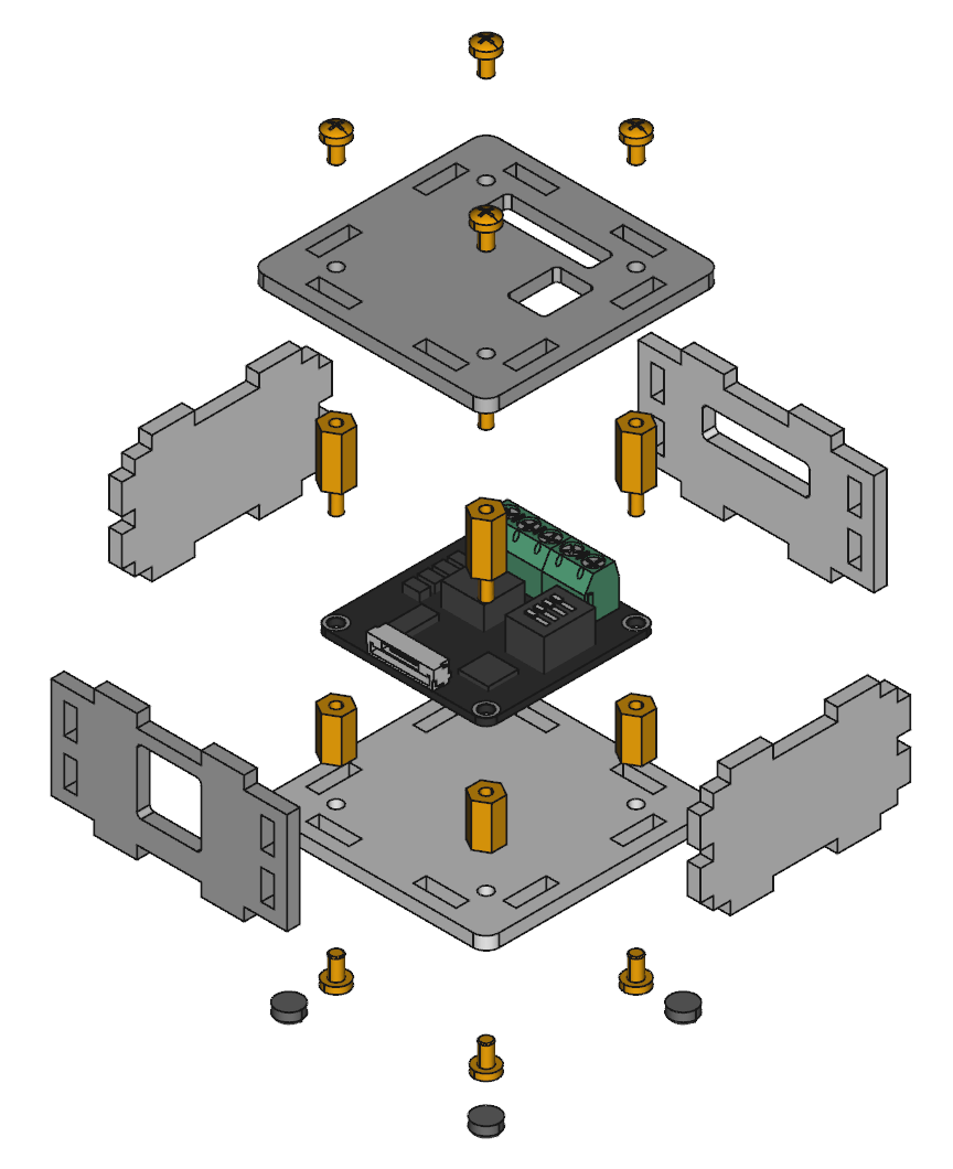
Hint: There is a protective film on both sides of the plates, you have to remove it before assembly.
Programming Interface
See Programming Interface for a detailed description.
Language |
API |
Examples |
Installation |
|---|---|---|---|
C/C++ |
|||
C/C++ for Microcontrollers |
|||
C# |
|||
Delphi/Lazarus |
|||
Go |
|||
Java |
|||
JavaScript |
|||
LabVIEW |
|||
Mathematica |
|||
MATLAB/Octave |
|||
MQTT |
|||
openHAB |
|||
Perl |
|||
PHP |
|||
Python |
|||
Ruby |
|||
Rust |
|||
Shell |
|||
Visual Basic .NET |
|||
TCP/IP |
|||
Modbus |